TR-2 Receiver
The information below on discontinued products is provided for individuals who are still using these older systems. Product descriptions may be time sensitive or even outdated. Please contact Telonics if you have questions.
Small and lightweight in design, the TR-2 covers a 2 MHz (2000 kHz) frequency band and accommodates approximately 180 transmitters, each separated by 10 kHz. Capacity may be increased to 360 or more transmitters with an extended frequency range option. (Note: There are specific frequencies that are not available on the TR-2. Consult the laboratory to confirm that this will not affect your reception when working with transmitters supplied by Telonics.)
The TR-2 offers precise digital vernier tuning, direct frequency display (frequency and channel are synonymous), and is designed to maintain high sensitivity and calibration accuracy under demanding field conditions. Advanced RF amplifier design provides four times the sensitivity and twice the operating range of many other receivers. High quality military specification reference crystals assure stability, and the triple conversion superheterodyne design offers exceptional dynamic range. Both very weak and strong signals can be controlled with ease and high resolution. The TR-2 has a self-contained power pack that can be recharged through AC wall current or a 12 VDC power source or storage battery. The Receiver combines with the TS-1 Scanner/Programmer for a system with fully automatic frequency selection. Special power supply options are available for a variety of applications.
Telonics TR-2 Includes the Following:
- RC-1 single-wide, heavy saddle leather carrying case
- RP-2 AC charger. Please specify 110-120 VAC, 50/60 Hz (RP-2-110) or 220-240 VAC, 50/60 Hz (RP-2-220)
- RP-3-12, 12-volt DC charge cord for vehicles
Note: The TR-2 may be purchased without the accessories.
Frequency Band
Specify choice of frequency band from list below: (other frequency ranges available upon quotation).
- 148.000 to 150.000 MHz
- 150.000 to 152.000 MHz
- 159.000 to 161.000 MHz
- 164.000 to 166.000 MHz
- 172.000 to 174.000 MHz
- 216.000 to 218.000 MHz
TR-2 Specifications
General: 2000 kHz coverage (3000 to 6000 kHz optional), direct frequency reading, low power consumption, synthesized triple conversion superheterodyne receiver with self contained power pack capable of recharging from AC wall current or any 12 VDC power source or storage battery.
Frequency coverage: any 2 MHz (2000 kHz) band in the 146 to 175 MHz range (standard bands are 148-150, 150-152, 159-161, 164-166, and 172- 174 MHz; special frequencies and wider band coverage are available on special order.)
Channel selection: 2000 (3000-6000 optional) 1 kHz channels easily selected with direct frequency reading controls on front panel
Delta frequency selection: totally crystal controlled with 10 kHz delta (fine) tuning (plus 9, minus 1 kHz increments provided)
Center frequency variation from 10 kHz channel to 10 kHz channel: <± 0.3 kHz
Frequency stability over internal voltage range: <± 0.1 kHz
Long-term frequency drift: (after one-minute stabilization) < 0.1 kHz
Acceptable modes of operation: pulse amplitude modulation (PAM), pulse interval modulation (PIM), continuous wave (CW), and single side band (SSB)
Battery life indication: front panel metering of battery voltage
Nominal current drain: 35ma (dependent upon gain control setting)
Typical operational time: to recharge, 10 hours; to replacement with optional alkaline batteries, 35-40 hours
External charging source: capable of recharging from any 12-20 VDC source which is capable of supplying 70 mA for 16 hours (1.12 AH)
Case polarity: negative (-) ground
RF input impedance: 50 ohms (for 3 dB maximum noise figure)
Noise figure: 2.5 dB typical, 3.0 dB maximum with 50 ohm source impedance
Input level for 10 dB S+N+D/N: -131 dBm maximum
Typical minimum discernible (input) level (MDL): -150 dBm (0.007 microvolts)
Image rejection: 50dB minimum, 60 dB typical
Dynamic range without adjusting gain control: 30-50 dB
Total gain range with MGC: > than 150 dB
Audio output impedance: 2-4 ohms (capable of use with headsets and speakers in the impedance range 4-20 ohms)
Internal speaker cut-out: Internal disconnect provided which mutes the front-panel speaker when headset plug is inserted.
Audio output plug required: standard 1/4 inch phone plug
RF input connector: BNC
External control and data output: provision for interfacing to an external frequency control source and for output of real time audio information to external processors
Operating temperature range: -40 to +70º C
Case construction: reinforced extruded aluminum
Dimensions: 4.6 x 2.0 x 7.1 inches (11.7 x 5.1 x 18.0 cm)
Weight: 1.9 lbs. (0.86kg)
Carrying case supplied with unit: heavy-duty water-repellent saddle leather with belt loop and padded shoulder strap hand-stitched with nylon thread and rivets
TR-2 Options, Modifications, and Power Supply Options
Prices are additive to the TR-2.
TR-2-E 4 MHz Extended Frequency Range Option for the TR-2 Receiver
Internal modification extends frequency coverage of the TR-2 Receiver from 2.0 MHz to 4.0 MHz. Capable of monitoring up to 400 channels with 10 kHz spacing.
- 148.000 to 152.000 MHz
- 150.000 to 154.000 MHz
- 158.000 to 162.000 MHz
- 163.000 to 167.000 MHz
- 164.000 to 168.000 MHz
- 172.000 to 176.000 MHz
- 216.000 to 220.000 MHz
Note: All frequency range extensions extend frequency coverage by adding a band of frequencies to the upper end of the existing band. For example, a 148-150 receive may be converted to 148-152 (TR-2-E). To expand the frequency coverage of a receiver to include frequencies below the existing band (e.g. 150-152 converted to 148-152); the receiver must have both a frequency conversion and a range extension.
TR-2-CON Conversion of TR-2 Receiver to Another 2 MHz Frequency Band
TR-2-M Enhanced Manual Gain Control
Allows direction-finding ability at very close ranges (where the signal appears to come from all directions).
TR-2-A External Power Modification
Allows user access to the battery compartment for installation of eight "AA" batteries via a removable cover on the side of the TR-2 or TDP-2 instruments. Supplied with eight "AA" alkaline batteries. In addition, an external 12-28 VDC power source can be utilized. There is not a battery charging circuit with this option. If rechargeable batteries are used, they must be removed from the receiver and charged separately. Modification is recommended where continuous operation from an external power source is required or where the TR-2 or TDP-2 will repeatedly be stored for several months or more between uses.
RP-1-A Replacement Rechargeable Nickel-Cadmium Power Pack
For TR-2 or TDP-2. Equipment must be returned to laboratory for installation of power pack.
RP-1-B Hatchback Battery Pack
For TR-2 or TDP-2. Allows user access to the battery compartment for installation of eight "AA" batteries via a removable cover on the side of the TR-2 or TDP-2 instruments. Supplied with eight "AA" alkaline penlight batteries. Charge circuit on receiver is retained for use with rechargeable Nickel-Cadmium batteries. Caution: Users must be sure NOT to attempt to recharge alkaline batteries. Equipment must be returned to laboratory for installation of hatchback.
RP-2-110 AC Charger
Charges TR-2 Receiver or TDP-2 Data Processor from 110-120 VAC, 50/60 Hz source.
RP-2-220 AC Charger
Charges TR-2 Receiver or TDP-2 Data Processor from 220-240 VAC, 50/60 Hz source.
RP-5 AC Step-Down Transformer
Converts 220-240 VAC, 50/60 Hz to 110-120 VAC. Allows use of RP-2-110 chargers with 220-240 VAC
power sources.
RP-3-12 12-Volt DC Charge Cord
Used to charge TR-2 Receiver or TDP-2 Data Processor from 12 VDC negative ground electrical system (e.g. an automobile battery). The plug on this cord requires a cigarette-lighter jack on the power source.
RP-3-24 24-28 Volt DC Charging Adapter
Allows charging of TR-2 Receiver or TDP-2 Data Processor from 24-28 VDC negative ground electrical system (e.g., an aircraft power supply). Must be used in conjunction with RP-3-12.
RP-4 Field Power Pack
12-volt, 5 ampere-hour field recharging source. Suitable for charging TR-2 Receiver or TDP-2 Data Processor, or for powering a data logger (110-120 VAC 50/60 Hz charger included). Black, high-impact polystyrene case. 90-day warranty.
Dimensions: 6.12 x 2.43 x 6.6 inches
Weight: 5 lbs
ADP-212 VDC, Two-Outlet "Y" Adapter
Cigarette-lighter plug on one end, two cigarette lighter jacks on the other
ADP-312 VDC, Three-Outlet "Y" Adapter
Cigarette-lighter plug on one end, three cigarette lighter jacks on the other.
RW-6-6 Power Harness Assembly
Cigarette lighter plug on one end and three coaxial power plugs on the other provide power to three instruments such as the TR-2/TS-1, TDP-2, and data logger from 12 VDC sources such as model RP-4.
Related Equipment
TS-1 Scanner/Programmer
The TS-1 offers programming and memory of up to 2000 discrete frequencies, and controls the frequency selection of the TR-2 Receiver over a 2.0 MHz bandwidth. (If using the extended frequency range TR- 2E, TR2-E-5, or TR2-E-6 options, manual switching is required to select a particular 2 MHz portion of the frequency band to be scanned). Frequencies are programmable to 1 kHz and scanning is automatic with three preset rates (approximately 0.6, 1.2 and 5 seconds dwell time on each channel with standard configuration) and reversible direction. Scanning is halted manually. Frequencies may be easily added or deleted at any time without modifying the balance of the program. A liquid crystal display (LCD) is easily read in direct sunlight, and provides real-time indication of each frequency being programmed or received. The TS-1 requires no batteries and derives all of its power from the TR-2 Receiver. Extremely low current drain permits the TS-1 to retain programmed frequencies in memory without substantial effect on the TR-2 batteries.
Each TS-1 Scanner is calibrated to a specific TR-2 Receiver. Initial installation of Scanner to Receiver must be done at the laboratory. Thereafter, the Scanner may be quickly plugged or unplugged from the Receiver in the field.
Telonics TS-1 Includes the Following:
- RC-2 double-wide heavy saddle leather carrying case (holds both the TR-2 and TS-1), with belt loop and shoulder strap.
Note: The TS-1 may be purchased without the case.
TS-1 Specifications
Memory capacity: 2000 frequencies within a 2 MHz band
Scanning sequence: numerically ascending or descending (selectable by front panel switch)
Programming resolution: 1 kHz
Frequency accuracy: 0.1 kHz
Dwell time per frequency: three speeds selectable by front panel switch; 0.6, 1.2, and 5 (± 10%) seconds standard, other speeds factory-selectable
Time required to load or delete a single frequency: instantaneous
Time required to add or delete all 2000 frequencies: 0.2 seconds
Memory and program retention: non-volatile when attached to receiver
Display: real-time, liquid crystal, reflective-type
Typical current drain: 2 ma
Batteries required: none (power is derived from the companion receiver)
Operating temperature range: -10 TO +40º C
Storage temperature range: -30 TO +60º C
Dimensions: 4.6 x 2.0 x 7.1 inches (11.7 x 5.1 x 18.0 cm)
Weight: 1.3 lbs. (580g)
Carrying case supplied with unit: heavy saddle leather, with belt loop and padded shoulder strap.
TS-1 Options and Modifications
Prices are additive to the TS-1.
TS-1-PBB Primary Battery Back-Up System for TS-1
Allows full memory retention when the Scanner is removed from the Receiver. Five-year life, internally installed in TS-1.
TS-1-CON Conversion of Scanner to Another Band
TS-1-CST Change in Scan Times
Labor and material costs vary depending on the scan times desired. Please contact the laboratory with your requirements for a quote if the ratio of the maximum and minimum scan times you desire does not exceed 100:1 (e.g. 500-second maximum, five-second minimum), and the maximum scan time does not exceed five minutes.
TS-1-ESC External Switching Control
Allows control of switching to next programmed frequency by pulling a +5V DC line to ground.
TNR2000 Noise Reduction Unit
For information on the TNR2000 (see fig. 2), click here
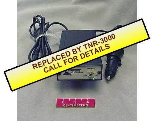
Fig. 2 - TNR2000 Noise Reduction Unit
Cases And Enclosures
Receiver Carrying Cases
RC-1 Receiver Case
Single-wide. Water-repellent saddle leather carrying case with belt loop and padded shoulder strap. Fits TR-2 Receiver or TDP-2 Processor.
RCC-1 Replacement Leather Cover for RC-1 Case
Specify measurement between snaps.
RC-2 Receiver/Scanner or Receiver/Processor Case
Double wide. Same as RC-1, except depth dimension accommodates TS-1 Scanner/Programmer or TDP-2 Data Processor in addition to TR-2 Receiver.
RCC-2 Replacement Leather Cover for RC-2 Case
Specify measurement between snaps.
RC-6 Triple-Wide Leather Case
Triple-wide. Same as RC-1, except depth dimension accommodates three instruments such as the TR-2, TS-1, and TDP-2.
RCC-6 Replacement Leather Cover for RC-6 Case
Specify measurement between snaps.
RCS-1 Replacement Leather Shoulder Strap for RC-1, RC-2, or RC-6 Cases
Underwater Receiver Housings
Click here for leaflet entitled, "Sexton Photographic Specifications for Environmental Housings for Telonics Equipment".
Instrument Cases
RC-3 Zero/Haliburton Instrument Case
Weatherproof metal instrument case with neoprene seal and key lock. Does not include foam interior. Provides portable weather-resistant housing for Data Acquisition System or other equipment. Dimensions: 25.25 x 17.25 x 9 inches (inside), 26 x 18 x 9.25 inches (outside) Weight: 11 lbs
RC-3F Custom-Cut Foam Interior for Zero/Haliburton Instrument Case
RC-4 Pelican Instrument Case
Water-tight, air-tight, dust-proof, lockable case with O-ring seal. Supplied with custom foam interior and O-ring sealed purge valve for quick pressure equalization after changes in altitude or temperature. Provides portable weather-resistant housing for Data Acquisition System or other equipment.
Dimensions: 22 x 17.25 x 7.75 inches (inside), 23.25 x 20.75 x 9 inches (outside)
Weight: 14 lbs
Headphones and Speakers
A set of quality headphones is required for reception of weak signals and for accurate direction finding work under marginal signal conditions. Built-in speakers in Telonics telemetry receivers are designed for monitoring purposes only, and not for direction finding or work under marginal signal conditions.
RH-2 Headphone
High quality, noise canceling, low impedance headphones designed for heavy use. Supplied with a straight cord, 0.25" plug, and foam filled ear seals. These headphones replace the RH-1 headphones.
RW-4A "Y" Adapter
Allows the use of two low impedance headsets (such as model RH-1) with a single receiver.
TAH-4 Cloth "Comfort Covers" (pair)
For TAH-2 headset and RH-1 headphones. Soft cloth covers fit over ear seals and permit air circulation in hot weather and insulation in cold weather.
TAH-5 Eyeglass Adapters (pair)
Soft foam spacers conform to both your head and the headphone ear seals to prevent noise leaks and pressure on the temples.
TAH-6 Replacement Cushion Ear Seals (pair)
For RH-1 headphones.
CON-PHN Dust Cover
For TR-2 phone jack.
SPK-1 Speaker
External speaker (2-1/4 inches W x 2-1/2 inches D) with mounting bracket, 6.5-foot cord, and 1/4 inch phone plug.
Service Commitment
Since 1970, Telonics has built a reputation based on product quality, product support, service, and customer satisfaction. Telonics strives to produce the highest quality products, and to support those products accordingly.
Because of extreme conditions and the unpredictable nature associated with most telemetry applications, problems occasionally arise. Most problems can be resolved quickly. In all cases, we hope to be able to work in partnership with users to resolve problems to the user's satisfaction and to uphold our demonstrated commitment to excellence. If problems should arise, all products must be returned to our factory for failure analysis.
Warranty - Show
Telonics warrants its products to be free from defects in material and workmanship for a period of one year from the date acquired. Telonics does not warrant batteries.
If a defect occurs, return the equipment to us within the proper time frame at the following address: TELONICS, 932 E. IMPALA AVENUE, MESA AZ USA 85204-6699. Damage to any equipment resulting from misuse, accidents, unauthorized service, extreme conditions, or other causes, is excluded from this warranty. Telonics does not assume responsibility for loss or damage to equipment during shipment. Telonics does not assume responsibility for delays resulting from shipment on commercial or private carriers. We insure all equipment shipped from our facility and suggest that shipments to Telonics also be insured.
Upon the timely return to our facility, if defective, the product will be replaced or repaired at our discretion at no cost to the customer. This remedy is the exclusive remedy. This product is supplied without any further warranties or conditions, expressed or implied, including warranties of merchantability, quality or fitness for particular reason or those arising by laws, statutes or trade usage or course of dealing.
The entire risk, as to the results and performance of the product, is assumed by the customer. Neither Telonics, nor its suppliers, shall have any liability to the customer or any other person or entity for any indirect, incidental, special, or consequential damage whatsoever, regardless whether Telonics has been told of the possibility of such damages or that such damages might be foreseeable. Telonics has no responsibility or liability for the claims of any third party. The maximum aggregate to the customer, of Telonics and its suppliers, shall not exceed the amount paid by the customer for the product.