Telonics TR-4 Receiver
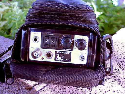
The TR-4 is a high performance, inexpensive telemetry receiver. It is small, lightweight, and designed for easy field use. The receiver can be tuned for operation within any user-specified 4 MHz band between 142 and 220 MHz. The TR-4 is microprocessor-controlled, allowing up to 100 channels to be programmed within the specified 4 MHz band. The TR-4 was designed for use in projects where a scanning receiver is not required.
The TR-4 is provided with:
- Programming Record showing the programmed frequencies for each channel
- PK002399 padded carrying case with shoulder strap, belt loop, and accessory pocket
- Two 9-volt alkaline batteries (installed in receiver)
- Lightweight "earbud-type" AU002432 earphones
The TR-4 Kit includes the items noted above and:
- TR-4 Channel Frequency Editor software, which allows the user to program channels in the TR-4 (an software authorization code will be provided with purchase, the software must be downloaded)
- TSC-10A Smart Cable, connects the TR-4 to the user's computer for programming channels
Notes on Usage - Show
- The TR-4 is switched "ON" by rotating the control knob labeled "GAIN" clockwise from the "OFF" position. As the gain control knob is continuously rotated clockwise, the gain of the receiver increases. When switching the receiver "OFF", be sure to rotate the gain control knob fully counter-clockwise until it clicks into the "OFF" position.
- The TR-4 is a microprocessor-controlled receiver which can include up to 100 channels. The center frequencies programmed into each channel on the receiver at the time of purchase are listed on an enclosure entitled "Telonics TR-4 Programming Record," which is provided with the TR-4. Channels are selected via the push-switches. The receiver can be fine-tuned over a range of at least +/- 5 kHz (typically, -7 to +5 kHz), relative to the center frequency for each channel through use of the "FINE-TUNING" knob. For example, if a channel is programmed to be 150.220 MHz, then fine-tuning would allow coverage of 150.215 to 150.225 MHz.
- To achieve maximum sensitivity with the TR-4, the incoming signal should be tuned to the high side of "zero-beat." This is accomplished by slowly rotating the tuning control clockwise while listening to a signal with the gain control set as low as possible. When properly tuned, the pitch or tone of the signal will increase in frequency as the tuning control is rotated clockwise. If the pitch decreases as the tuning control is rotated clockwise, continue clockwise rotation through the zero beat (commonly noted as a dull thud, or "plop" sound) until the pitch increases with further clockwise rotation. The ideal tuning point is an 800-1000 Hz tone. If proper tuning cannot be reached prior to full clockwise rotation, it may be necessary to switch to an alternate channel. See the Programming Record for the particular frequency assignments for each channel on the individual TR-4 to select the most appropriate channel.
- The receiver is powered by either one or two 9-volt alkaline batteries, or by an external source. The batteries are not rechargeable and should be replaced when the "LO BAT" indicator on the front panel becomes lighted. (It is normal for this indicator to flash briefly as the receiver is turned off.) To replace the batteries, remove the small panel on the side of the receiver and snap out the old batteries. Replace with new 9-volt alkaline batteries, making sure that the batteries are positioned as shown by the polarity markings inside the battery compartment. Installing a 9-volt battery with polarity reversed will not contribute power to the TR-4; however, it will not damage the receiver nor will it discharge the battery. Some users may wish to install one of the two batteries in this manner to act as a spare, which can be readily reversed in the field in the event that the low battery indicator becomes illuminated. Suitable 9-volt alkaline batteries for the TR-4 include Energizer and Duracell brand names (batteries may be cross-referenced using the NEDA/ANSI Part Number 1604A).
- When powering the receiver from an external source, a coaxial power plug must be inserted into the jack labeled "EXT 12V" on the front panel. Telonics power cord PS00338-002 should be used when powering the TR-4 from a 12-volt DC source; this cord is terminated with a car auxiliary power "cigarette-lighter" plug. Telonics power cord PS009736-001 should be used when powering the receiver from 110-240 VAC, 50-60 Hz "wall" supply. These power cords may be purchased separately.
- A BNC female connector labeled "ANT" is provided on the front panel. The coaxial cable used to connect the receiving antenna to the receiver should be a 50 ohm cable, with a BNC male connector. A variety of directional and omni-directional antennas may be utilized with the TR-4, and the optimal antenna depends on the user's application. All antennas should be specifically tuned to match the reception band of your receiver. Telonics RA-2AK or RA-23K 2-element “H” antennas are well suited for many tracking applications. Contact Telonics for recommendations regarding antennas.
- We strongly recommend use of headphones, which allow detection of weaker signals and will make direction finding easier. The "PHONES" jack on the TR-4 is designed for a 1/8 inch, stereo or monaural plug, and audio output impedance is approximately 30 ohms. Lightweight headphones are provided with the TR-4. Other headphones or earphones with the appropriate impedance and plug can alternatively be utilized to suit the user's preference.
Specifications - Show
| General | low power consumption, synthesized dual conversion super heterodyne receiver |
|---|---|
| Frequency coverage | up to 100 channels, selectable by user, within a band of 4 MHz |
| Channel selection | push-button controls on front panel |
| Fine tuning | ±5 kHz via front panel control |
| Center frequency variation relative to specified frequency | ±0.3 kHz |
| Frequency stability over internal voltage range | ±0.1 kHz |
| Long term frequency drift | (after one-minute stabilization) ±0.1 kHz |
| Selectable Bandwidth (-6dB) | 0.8 kHz |
| Acceptable modes of operation | pulse amplitude modulation (PAM), pulse period modulation (PPM), continuous wave (CW), and single side band (SSB) |
| Low battery indication | front panel |
| LED nominal current drain | 50-55 mA (dependant upon gain setting) |
| Power supply | Internal power supply: 6-12 VDC required. Battery compartment accommodates up to two 9-volt alkaline batteries. External power supply: 12-30 VDC source with negative ground and center pin positive. Note: If front panel input voltage drops below ~11V, the receiver will begin to draw power from the batteries, if installed. If batteries are not installed (or are installed backwards) the practical front panel power supply voltage range is increased to ~8V - 18V. TR-4 front panel power jack accepts a standard barrel power connector: Plug Dimensions: 2.1mm ID / 5.5mm OD / 9.5mm barrel length |
| Typical time to battery replacement | eight hours with one battery, 16-18 hours with two batteries (at 21° C). |
| RF input impedance | 50 ohms |
| Noise figure | 2.5 dB typical, 3.0 dB maximum with 50 ohm source impedance |
| Input level for 10 dB S+N+D/N | -131 dBm maximum |
| Typical minimum discernible input level | -150 dBm (0.007 microvolt) |
| Image rejection | 30dB minimum |
| Dynamic range without adjusting gain control | 60 dB |
| Total gain range | 130-140 dB |
| Audio output impedance | 30 ohms |
| Internal speaker cut out | front panel speaker is muted when plug is inserted in headphone jack |
| Audio output plug required | 1/8 inch stereo or monaural phone plug |
| Front panel RF input connector | BNC jack |
| Operating temperature range | -40° C to +70° C (alkaline batteries may be unusable below approximately -30° C) |
| Dimensions | 6.75 x 3.5 x 1.75 inches (17 x 9 x 4.5 cm) |
| Weight | 425g, including two batteries |
Information Required When Ordering a TR-4
Related Products
- VHF Receiving Antennas: An appropriate antenna is required for use with the TR-4. For hand-held tracking a directional antenna such as the RA-2AK or RA-23K is recommended. A omni-directional antenna, such as the RA-5A can also be very useful in some applications.
- TR-4 Channel Frequency Editor software, which allows the user to program channels in the TR-4 (CD-ROM)
- TSC-10A Smart Cable, connects the TR-4 to the users PC for programming channels
- PS000338-002 12 Volt DC Power Cord with car power outlet ("cigarette-lighter" style) plug
- PS009736-001 110-240 Volt AC Power Cord
- TNR 3000 Telonics Noise Reduction Unit
Service Commitment
Since 1970, Telonics has built a reputation based on product quality, product support, service, and customer satisfaction. Telonics strives to produce the highest quality products, and to support those products accordingly.
Because of extreme conditions and the unpredictable nature associated with most telemetry applications, problems occasionally arise. Most problems can be resolved quickly. In all cases, we hope to be able to work in partnership with users to resolve problems to the user's satisfaction and to uphold our demonstrated commitment to excellence. If problems should arise, all products must be returned to our factory for failure analysis.
Warranty: TR-4
Telonics warrants the TR-4 to be free from defects in material and workmanship for 90 days (see Extended Warranty below) from the date acquired. Telonics does not warrant batteries.
If a defect occurs, return the equipment to us within the proper time frame at the following address: TELONICS, 932 E. IMPALA AVENUE, MESA, AZ USA 85204-6699. Damage to any equipment resulting from misuse, accidents, unauthorized service, extreme conditions, or other causes, is excluded from this warranty. Telonics does not assume responsibility for loss or damage to equipment during shipment. Telonics does not assume responsibility for delays resulting from shipment on commercial or private carriers. We insure all equipment shipped from our facility and suggest that shipments to Telonics also be insured.
Upon the timely return to our facility, if defective, the product will be replaced or repaired at our discretion at no cost to the customer. This remedy is the exclusive remedy. This product is supplied without any further warranties or conditions, expressed or implied, including warranties of merchantability, quality or fitness for particular reason or those arising by laws, statutes or trade usage or course of dealing.
The entire risk, as to the results and performance of the product, is assumed by the customer. Neither Telonics, nor its suppliers, shall have any liability to the customer or any other person or entity for any indirect, incidental, special, or consequential damage whatsoever, regardless whether Telonics has been told of the possibility of such damages or that such damages might be foreseeable. Telonics has no responsibility or liability for the claims of any third party. The maximum aggregate to the customer, of Telonics and its suppliers, shall not exceed the amount paid by the customer for the product.
Extended Warranty
Two extended warranties for the TR-4 are available at additional cost when the TR-4 is originally purchased.
- One-year warranty extension extends the above warranty by a period of one year (i.e., to 15 months from the date the receiver is shipped from our laboratory at the time of original purchase).
- Three-year warranty extension: extends the above warranty by a period of three years (i.e., to 39 months from the date the receiver is shipped from our laboratory at the time of original purchase).
Non-Warranty Service
If problems are encountered outside the warranty period, or if non-warranty service is required, send the receiver and a description of the problem and/or service to be performed to our laboratory. Shipping charges to our laboratory must be prepaid. We will perform the required service and return the receiver to the address specified. Labor charges and parts will be charged at current rates, and return shipping charges will be added to the invoice.