Implantable VHF Systems
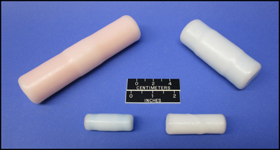
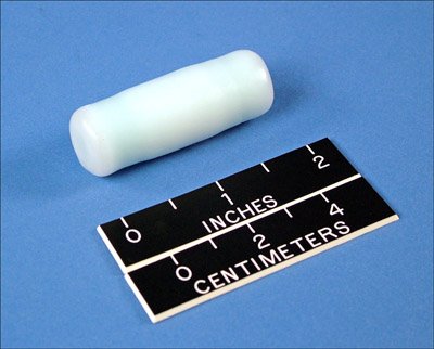
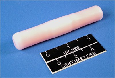
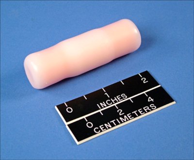
IMP-130, IMP-200, IMP-400, and IMP-700 implantable transmitters
Although most VHF telemetry involves transmitters attached to animals externally via collars, harnesses, or other means; implantable transmitters are a favored option in some applications. Some species, such as otters, do not wear collars well and harnessing techniques have been shown to be ineffective or harmful, so implants are used. Snakes, lizards, and fish are also commonly instrumented using implants. Implants can provide a method to measure body temperature, heart rate, or other physiological parameters; and have been used to detect parturition, the onset of disease processes, or estrous. Implants have also been used where there was concern about how an external device might influence interactions with predators, conspecifics, or offspring. In some behavioral studies and in some areas with high human visitation implants are preferred because there are no external marks or devices. Implants have also been used on young, rapidly growing animals.
In general it has been noted that implants are well tolerated; however, if you are considering or select an implant, Telonics recommends that you review appropriate literature and consult with the entities responsible for animal care and health at your institution or agency.
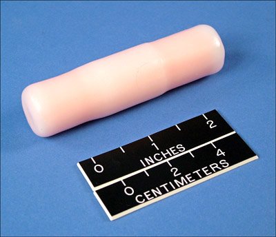
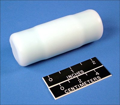
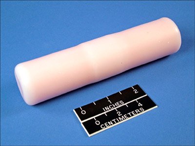
IMP models use Telonics standard VHF transmitter electronics (MK-11 or MK-12) and include a completely internal coiled antenna.
IMP Models
| Model |
Dimensions
L x Dia (in, cm) |
Weight (g) |
Battery Life (months) |
| IMP-130-2 |
2.1 x 0.75
5.3 x 1.9 |
19 |
5.0 |
| IMP-140-2 |
3.3 x 0.75
8.4 x 1.9 |
40 |
11.0 |
| IMP-200-2 |
2.5 x 0.9
6.4 x 2.3 |
25 |
9.0 |
| IMP-210-2 |
3.0 x 0.9
7.6 x 2.3 |
38 |
9.0 |
| IMP-310-2 |
3.3 x 0.9
8.4 x 2.3 |
38.5 |
12.5 |
| IMP-400-2 |
4.0 x 1.3
10.2 x 3.3 |
~95 |
36.0 |
| IMP-700-2 |
6.1 x 1.3
15.5 x 3.3 |
~158 |
43.0* |
Battery lives for IMP models are calculated using Telonics Product Programmer (TPP), with assumptions of 60 beats per minute and operation 24-hours per day at 30°C. IMP-400-2 and smaller implants are indicated at standard power, the IMP-700-2 is indicated with a high-power option.
Key Features of IMP Models
- IMP models have a dual water barrier, a sealed polycarbonate tube coated in wax; which completely encloses the transmitter electronics, power supply and the transmitting antenna. This design makes the implant less subject to mechanical damage and reduces the chance for moisture penetration over the life of the transmitter.
- Although implants often have less range than externally mounted units, Telonics "tunes" the implant's antenna to match to the dialectic of the body maximizing range performance of the system.
- The IMP-210-2 is designed as a rumen implant, with added weight compared to the IMP-200-2.
- Transmission power levels are selectable to accommodate either greater range or greater life; although, low power options are not normally used with implants.
- Customized transmission duty cycling (on/off periods) is available, including seasonal cycles which can vary throughout the life of the transmitter. All timing is controlled by a Real-Time-Clock, which allows seasons to start and end on any desired calendar date and time, and sensor data to be accurately time stamped.
- MS6 mortality-motion sensing option is available at no additional charge. Other sensor options are available, including the MA activity option, MS4 temperature option, and MS5 temperature-triggered mortality option (sensor descriptions are provided below).
- Data Logging Option 350 is available to store mortality, activity, and/or temperature data in transmitter memory for download if the transmitter can be recovered.
Sensor Options for VHF Transmitters using the MK-11 or MK-12 Electronics
MK-11 or MK-12 Sensor Options - Show
Current Telonics VHF transmitters use either the MK-11 or MK-12 electronics. Sensor options available with these transmitters are described below grouped by primary use: mortality, activity, and temperature monitoring. There is some overlap between sensor types and how they are used, with typical uses as described. If you have questions about sensors or how they might best be implemented in your study please call Telonics to discuss your application.
Changes in motion or temperature are detected by unit's sensors and result in changes in the units transmitted pulse period. Pulse period is the time between the start of one transmitted pulse and the start of the next transmitted pulse, and it is measured in milliseconds (ms). Pulse rate in beats per minute (bpm) = pulse period/60,000.
With inclusion of the Data Logging Option, sensor data can also be stored-on-board the transmitter and downloaded using Telonics Data Converter (TDC) at the end of the study if the transmitter can be recovered.
Both the MS6 mortality-motion option and the MA activity option use an on-board accelerometer as the sensor to detect changes in position and acceleration in three axes. The sensor is sampled and each second is classified as active or not depending on whether a change in position or acceleration has been detected in that second.
The MS4 temperature option and MS5 temperature-triggered mortality option are based on an on-board thermistor used to measure temperature.
The MS6 mortality option can be enabled in conjunction with the MA activity sensor or MS4 temperature sensor. In such cases the activity or temperature sensor will be used to determine the active/alive pulse period.
Other sensors cannot simultaneously be used to control the transmitted pulse period, but if the Data Logging Option is purchased, multiple sensing options (e.g. MA activity and MS4 temperature) can be purchased and their resultant data stored-on-board the transmitter.
Mortality Sensing Options:
Mortality - Motion sensor (MS6)
This option provides active/alive and inactive/mortality pulse periods. Depending on the length of time over which activity is evaluated (time-out interval), this sensor can be thought of as either a mortality sensor (e.g. timeout interval of 4-12 hours) or as a motion sensor (e.g. with a timeout interval of seconds to minutes). Typically it is used as a mortality sensor, which is the most common sensor option used.
Users specify the following:
- Time-out interval over which the active versus inactive evaluation is made,
- Minimum number of active seconds to keep the transmitter in the active pulse rate (5 seconds is the default),
- Active pulse rate or period,
- Inactive pulse rate or period.
For example, if the time-out was defined as 6 hours, the default 5 active seconds was used, active pulse period was 1000ms (60 bpm), and inactive pulse period was 600ms (100 bpm); then as long as there were at least 5 active seconds in the preceding 6 hours, the pulse rate would be 60 bpm. If 6 hours elapsed with fewer than 5 active seconds the pulse rate would shift to 100 bpm. If ≥ 5 active seconds were again detected within any 6 hour window (e.g. if a scavenger moves the transmitter), the pulse rate would immediately switch back to 60 bpm.
When used as a mortality sensor, the active pulse rate is typically set to a comfortable tracking rate (often ~50-60 bpm), and the inactive/mortality pulse rate is faster. This helps conserve battery life because the active rate will be common, and the inactive rate rare. Users may alternatively select a slower inactive rate; for example, such programming is commonly used on bears which hibernate and are inactive for long periods of time.
If this sensor is used with short time-out intervals (e.g. minutes rather than hours), it serves as a motion sensor, rather than a mortality sensor. Operation is as noted above, but the inactive mode would be triggered much more frequently than with long time-outs. Such short time-outs are uncommonly used, but with an example application being to help determine the effect of disturbances on resting animals by having the inactive rate triggered after a few minutes of inactivity, but with the active rate immediately triggered if the animal is startled and begins moving.
When the MS6 option is activated, date and time of the most recent 9-16 changes from active to inactive or back are stored by the transmitter. This data can be downloaded using Telonics Product Programmer (TPP).
The MS6 option can alternatively be selected to provide information on how long it has been since the animal died or became inactive by having the inactive/mortality pulse periods related to how long the transmitter has been in that mode. If ordering the option with this feature, four additional values are specified:
- Maximum elapsed time of concern after mortality is detected (up to 1000 days),
- Pulse period that corresponds to the specific time when mortality is detected,
- Pulse period that corresponds to the maximum time of concern after mortality is detected,
- Whether a simple linear scale or a segmented scale of 2-8 pieces is used. A linear scale provides constant resolution over the defined range of pulse periods. A segmented scale allows finer resolution of elapsed time immediately after mortality is detected and coarser resolution later on. Each segment has resolution that is twice as coarse as the segment before it. Telonics provides a graph and linear equations to convert an observed pulse period into an elapsed time.
Temperature-Triggered Mortality option (MS5)
This option is designed to change pulse period/rate when measured temperature drops below a user-specified value. If temperatures rise back above the defined value, pulse period will change back to the default/higher temperature period. A typical use would be to detect mortality in an implantable transmitter in an endothermic animal, where temperature rather than motion could be a better indicator of mortality. For example, it has been used in waterfowl where waves could prevent a motion-based mortality sensor from detecting mortality. Another use of this option has been in vaginal implants to determine parturition, where the temperature would drop and the pulse period change when the unit was expelled. This option might not be suitable in areas where a high ambient temperature prevents the transmitter from cooling after death or parturition.
Users specify the following:
- trigger point temperature
- pulse period above the trigger point temperature
- pulse period below the trigger point temperature
With this option, an alternative is to have a range of pulse periods determined by how long it has been since the animal died (temperature dropped below the defined threshold). This operates as described above for the MS6 sensor.
Activity Sensing Options:
Activity Sensor (MA)
This option adjusts pulse period based on the amount of activity within a user-defined interval. The pulse period can either be defined as one of two periods (active versus inactive) or scaled over a range of pulse periods. Changes in pulse period step through time; e.g. the amount of activity in interval 1 determines the pulse period in interval 2, activity in interval 2 determines pulse period in interval 3, and so on. Thus, the pulse period being transmitted always reflects the amount of activity in the prior activity data collection interval. This is illustrated in tabular form below.
| Collecting data for interval X |
Collecting data for interval X+1 |
Collecting data for interval X+2 |
Collecting data for interval X+3... |
| Transmitting pulse period from interval X-1 data |
Transmitting pulse period from interval X data |
Transmitting pulse period from interval X+1 data |
Transmitting pulse period from interval X+2 data... |
Active/Inactive mode: In each defined interval, one of two pulse periods is transmitted depending on the amount of activity in the proceeding interval.
Users specify the following:
- Classification interval (1-second default, but selectable between 1-255 seconds)
- Active pulse period,
- Inactive pulse period,
- Time interval over which data is evaluated (up to 100 minutes)
- Number of active classification intervals (typically seconds) required for the time interval to be considered active. If any activity is detected during the defined classification interval that interval is considered active.
For example, the classification interval could be defined as 1-second, active pulse period 1000ms (60 bpm), inactive pulse period 1500ms (45 bpm), the time for accumulation of data as 1-minute, and the number of active seconds required to designate as active as 10 seconds. In this case the VHF would operate at either 45 or 60 bpm depending on whether the number of active seconds was <10 or ≥10 in the prior 1-minute accumulation period.
Scaled pulse period mode: In each defined interval, pulse period is scaled within a user-defined range based on the amount of activity in the preceding interval.
Users specify the following:
- Classification interval (1-second default, but selectable between 1-255 seconds),
- Range of pulse periods to be used for scaling,
- Time interval (1 second up to 18 hours) over which activity is evaluated.
For example, the classification interval could again be 1-second, data could be summed over a 10-minute time interval, and the range of possible pulse periods could be 1000-3000. In such case, pulse periods would vary between 1000 and 3000ms (60-20 bpm) depending on the amount of activity in the prior 10-minute accumulation period. Increased levels of activity would result in shorter pulse periods.
With this option the user can also select whether the relationship between activity and period is linear or a segmented scale (with 2-8 segments). A linear scale provides a constant resolution between the number of active classification intervals and pulse period over the specified range. Segmented scales provide different resolution for each segment, with the first segment (starting at 0 activity counts) having the best resolution, and each following segment with resolution that is twice as coarse as the segment before it. Telonics provides a graph and linear equations to convert an observed pulse period into a number of "active classification intervals" over the update period.
Mortality - Motion Sensor Option (MS6)
If this sensor is used with short time-out intervals (e.g. minutes rather than hours), it serves as a motion sensor, rather than a mortality sensor. Operation is as noted in the more detailed description under Mortality Sensing Options above, but the inactive mode would be triggered much more frequently than with long time-outs. An example of such use is to help determine the effect of disturbances on resting animals by having the inactive rate triggered after a few minutes of inactivity, but with the active rate immediately triggered if the animal is startled and begins moving.
Temperature Sensor (MS4)
This option measures temperature at a defined sampling interval and causes pulse period to change with changes in temperature. Telonics provides a graph and linear equation to convert an observed pulse period into a temperature. Temperature sensing transmitters have uncalibrated accuracy shown in the table below. If higher accuracy is desired, the user can calibrate individual units.
Users specify the following:
- Sampling interval (1 second to 18 hours),
- Low-end temperature of concern with a corresponding pulse period,
- High-end temperature of concern with a corresponding pulse period.
Option 400 is the standard version of this sensor. It has a thermistor mounted on the electronics board (thus measuring internal package temperature, which may differ from either ambient or body temperature), and is centered at 37°C.
Option 401, is similar to Option 400, but the thermistor is centered at 14°C.
If you have a need for an externally mounted thermistor, please contact Telonics to discuss your application.
Sensor details:
| Opt: 400 (onboard) - Thermistor centered at 37° C |
|---|
| Range = -40 to +70° C |
|---|
| Resolution: | 1.041° @ -40°
0.087° @ +37°
0.162° @ +70° |
| Uncalibrated accuracy: | ±0.47° typ, ±3.35° max |
| Range = +14 to +47° C |
|---|
| Resolution: | better than 0.1° |
| Uncalibrated accuracy: | ±0.28° typ |
| Calibrated accuracy: | ±0.09° typ (plus cal error) |
| Opt: 401 (onboard) - Thermistor centered at 14° C |
|---|
| Range = -40 to +70° C |
|---|
| Resolution: | 0.39° @ -40°
0.076° @ +14°
0.342° @ +70° |
| Uncalibrated accuracy: | ±0.39° typ, ±2.0° max |
| Range = -10 to +32° C |
|---|
| Resolution: | better than 0.1° |
| Uncalibrated accuracy: | ±0.28° typ |
| Calibrated accuracy: | ±0.08° typ (plus cal error) |
Calibration, if desired, is the responsibility of the user, consisting of a 1-point calibration at the listed temperature.
Data Logging Option (Option 350) - Show
The Data Logging Option for MK-11 and MK-12 transmitters (Option 350) allows sensor data from the MS6 mortality-motion sensor, MA activity sensor, and/or the MS4 temperature sensor to be stored in transmitter memory and made available for download if the transmitter is able to be retrieved at the end of a study. Additional information regarding how these sensors work is provided in the Sensor Options section below. This option requires use of Telonics Data Converter to download the stored data.
For the MS6 motion-mortality sensor, the data logging records each date and time the sensor switches from active/alive to inactive/mortality or back. Assuming that no other sensor measurements are being stored, the data log can accommodate about 0.5 million transitions. Note that smaller units may not have sufficient battery capacity to fill the memory. The most recent 9-16 such transitions are recorded even without this option, but this option stores all such transitions.
For the MA activity sensor, the data logging option stores accelerometer data at user-defined intervals. These intervals may be the same throughout the anticipated life of the transmitter or they may change "seasonally". The activity data recorded is the number of active seconds (or other defined classification interval) during a defined collection interval. For example the number of active seconds in a one hour collection interval would be saved as a number between 0-3600. Assuming that no other sensor measurements are being stored, the data log can accommodate about 2.0 million measurements based on 30sec, 1 minute, or 5 minute intervals or about 1.3 million based on longer intervals. The activity collection schedule for data logging is independent of any activity schedule selected to control pulse rate.
For the MS4 temperature sensor, the data logging option stores temperature data at user-defined intervals (in 0.16°C increments). These intervals may be the same throughout the anticipated life of the transmitter or they may change "seasonally". The data log can store an estimated 1.3 million measurements if no other sensor data are stored. The temperature collection schedule for data logging is independent of any temperature schedule selected to control pulse rate.
Specifications for Transmitter Electronics
MK11/12 Transmitter General Specifications - Show
MK-11 and MK-12 beacons are microprocessor controlled pulsed-CW transmitters, designed for operation within the 137 - 225 MHz frequency range. Each MK-11 beacon transmits on a single, field-programmable frequency (within the frequency range that is ordered). MK-11 beacons also support 3 field-programmable power levels. The MK-12 beacon is crystal based, and therefore each beacon is built to operate on a specific frequency and with a specific power output (four power levels to choose from when ordering).
| Frequency Range |
MK11:
137 - 143 MHz (option 700),
143 - 156 MHz (option 710),
154 - 164 MHz (option 720),
162 - 174 MHz (option 730),
164 - 182 MHz (option 740),
182 - 201 MHz (option 750),
201 - 222 MHz (option 760)
MK12:
140 - 225 MHz
|
| Frequency Tolerance |
MK11:
Calibration: ±3 ppm max at room temperature / ±5 ppm from -40° to +70°C
Aging: <1ppm/yr
Shock: <1ppm 3000g x 0.2ms x ½ sine x 3 directions
MK12:
Calibration: ±17 ppm at room temperature / ±25 ppm from -40° to +70°C
Load: <7ppm typical for VSWR < 6:1
Supply Voltage: <3ppm typical over supply voltage range at 25°C
Aging: <1ppm/yr
Shock: <1ppm 3000g x 0.2ms x ½ sine x 3 directions
|
| VSWR Stability |
MK11: RF output stable to 10:1 VSWR, all phases.
Radiated harmonic levels are degraded with poor load VSWR.
Spurious emission specification maintained for > 10:1 VSWR.
MK12: RF output stable to 5:1 VSWR, all phases.
Radiated harmonic levels are degraded with poor load VSWR.
Spurious emission specification maintained for > 5:1 VSWR.
|
Output Power
|
| MK11: Field Programmable using TPP |
| Transmit Power |
Peak Power Output
Relative to Medium Power |
| Low |
0.5 * Medium Power |
| Med |
|
| High |
2.0 * Medium Power |
| MK12: Ordering Options for Power Level |
| Option |
Transmit Power |
Peak Power Output Levels
Relative to Standard Power |
| 200 |
Low (Temperature > -20°C) |
0.5 * Medium Power (Higher efficiency) |
| 202 |
Low |
0.5 * Medium Power |
| 204 |
Medium |
|
| 206 |
High |
2.0 * Medium Power |
Output power is measured into 50 Ω load. Effective Isotropic Radiated Power (EIRP) varies, depending on packaging, antenna configuration, and immediate environmental conditions.
|
| Emission Designator |
MK11: 2k00P0N -
California users: These transmitters meet the California requirement of EIRP < 0.0009W for all conditions.
MK12: 1k00P0N -
California users: These transmitters exceed the emission designator requirement of 2k00P0N for operation in California. The 1k00P0N emission designator is identical to the 2k00P0N except that it occupies only half of the 2 kHz bandwidth allowed by the State of California for wildlife tracking.
|
| Harmonic and Coherent Spurious Suppression |
MK11: <-30 dBc into 50Ω load
MK12: Coherent Spurious <-10 dBc |
| Spurious Suppression |
MK11: <-35dBc typical at > 10kHz offset from carrier
MK12: Non-Coherent Spurious <-50 dBc
|
| RF Pulse Width |
15 msec standard
Can optionally be configured from 10 - 250 msec
|
| Pulse Period |
Configurable from 250 - 5000 msec (12-240 Bpm) |
| RTC Accuracy / Seasonal Timing |
Temperature Compensated:
± 12min/yr max |
| Temperature Range |
-40°C to +70°C (Note: Temperature range is for the transmitter only. The power supply must provide the required peak current and voltage requirements for the transmitter over the expected temperature range.) |
| Shutdown Component |
Externally shutdown by presence of a small magnet |
Available Sensors
|
MS6 Mortality - Motion Sensor
MA Activity Sensor
MS4 Temperature Sensor
MS5 Temperature-triggered Mortality Sensor
Sensor descriptions available separately
|
Sterilization or Disinfection
The physiological wax coating implantable transmitters can melt at high temperatures, so treatment with a cold sterilant or disinfectant is recommended prior to implantation.
For additional information on sterilization/disinfection see Telonics Quarterly - Vol 7 No. 3.
Units should also be stored at room/body temperatures, including during transportation in vehicles.
Legacy Products
This information on discontinued products is provided for individuals who are still using these older systems. Product descriptions may be time sensitive or even outdated. Please contact Telonics if you have questions.
Telonics supports these products as possible based on availability of parts, software, or other considerations; but no longer sells them new.
Service Commitment
Since 1970, Telonics has built a reputation based on product quality, product support, service, and customer satisfaction. Telonics strives to produce the highest quality products, and to support those products accordingly.
Because of extreme conditions and the unpredictable nature associated with most telemetry applications, problems occasionally arise. Most problems can be resolved quickly. In all cases, we hope to be able to work in partnership with users to resolve problems to the user's satisfaction and to uphold our demonstrated commitment to excellence. If problems should arise, all products must be returned to our factory for failure analysis.
Warranty: Implantable VHF Transmitting Subsystems - Show
The Implantable VHF Transmitting Subsystem includes the following main components: internal digital and radio frequency electronics comprising the transmitter, power supply (battery), exterior packaging, physiologically compatible coating, and transmitting antenna. A refurbished Subsystem is warranted as if the Subsystem was purchased new, unless otherwise stated.
Telonics warranties only the following with respect to the Subsystem:
1.1 The "L" series standard implants are warranted in the following manner. The internal electronics (excluding batteries) are warranted to be free from defects in materials and workmanship and to perform to the operational specifications over the specified operating temperature range as published by Telonics for the rated operational life of the Subsystem (as recorded on the final test data sheet accompanying the unit), up to a maximum of one (1) year from the date of initial shipment of the Subsystem by Telonics.
1.2 The exterior packaging integrity of all implants with internal antennas are warranted for the full operational life of the Subsystem, up to a maximum of one (1) year from the date of initial shipment of the Subsystem by Telonics.
1.3 The exterior packaging integrity of implantable CHP subsystems with external antennas are warranted for the operational life of the Subsystem, up to a maximum of three (3) months from the date of initial shipment of the Subsystem by Telonics.
Limitations:
Although each Subsystem is supplied with a power supply in the form of a battery, Telonics does not manufacture batteries (electrochemical cells), and therefore cannot warranty the battery lifespan, mechanical integrity or other battery performance issues. However, Telonics conducts extensive testing of all types of electro-chemical subsystems to determine suitability to the application. Once an electrochemical system is chosen for a configuration, testing procedures are employed at Telonics to evaluate every individual battery that is installed in each transmitting subsystem. Even using these advanced testing procedures it is not possible to determine a specific battery's lifespan or mechanical integrity.
Telonics conducts tests to assure that each unit is transmitting at the power level selected by the user. Actual range performance is a system characteristic dependent upon numerous conditions including receiver sensitivity and noise figure, receiving antenna tuning and pattern, transmitter antenna integrity, line of sight conditions in the field, and vegetation and habitat conditions and other factors specific to individual study sites. Therefore it is not possible to warranty a minimum range that will be achieved for units deployed in the field.
"Packaging integrity" as applicable to 1.2 and 1.3 above, is limited to normal wear as encountered when implanted in the animal. Fatigue and/or breakage of the electrode leads used in heart rate transmitters are not covered under warranty.
It is the purchaser's obligation to make certain that it orders the correct size and type of Subsystem for the particular type and size of animal that the Subsystem will be applied to, and no warranty is expressed or implied for any failure to meet operational specifications due in whole or in part to use of an incorrect size or type of Subsystem.
No warranty is expressed or implied with regard to abnormal events or damage due to human actions such as gunshot damage, vehicle encounters, etc. Further, no warranty is expressed or implied with regard to damage resulting from misuse, accidents, unauthorized service, extreme conditions, or other causes not specifically enumerated herein.
The entire risk, as to the results and performance of the Subsystem, is assumed by the customer. Neither Telonics, nor its suppliers, shall have any liability to the customer or any other person or entity for any indirect, incidental, special, or consequential damage whatsoever, regardless whether Telonics has been told of the possibility of such damages or that such damages might be foreseeable. Telonics has no responsibility or liability for the claims of any third party. Telonics' and its suppliers' maximum aggregate liability shall not exceed the amount paid by the customer for the Subsystem.
Exercising the Warranty
If a defect occurs, return the Subsystem to Telonics within the applicable time frame noted above at the following address: TELONICS, 932 E. IMPALA AVENUE, MESA AZ USA 85204-6699. Telonics does not assume responsibility for loss or damage to equipment during shipment. Telonics does not assume responsibility for delays resulting from shipment on commercial or private carriers. We insure all equipment shipped from our facility and suggest that shipments to Telonics also be insured. Customer shall arrange for and pay all shipping, insurance and related charges incurred in the shipment of Subsystems to and from Telonics under this warranty.
Upon the timely return to our facility within the applicable time frame noted above, if the exterior packaging integrity and/or internal electronics (excluding batteries) are defective, the Subsystem will be replaced or repaired, at Telonics' sole discretion, at no cost to the customer, other than shipping charges. This remedy is the exclusive remedy. This product is supplied without any further warranties or conditions, expressed or implied, including warranties of merchantability, quality or fitness for particular reason or those arising by laws, statutes or trade usage or course of dealing.
The above warranty extends only to the original purchaser and does not cover any Subsystem which is resold or otherwise transferred from the original purchaser to another party. The warranty will be extended to customers who purchase the Subsystem directly from a Telonics-authorized distributor.