TR-5 Telemetry Scanning-Receiver
with Optional Data Acquisition System
The information below on discontinued products is provided for individuals who are still using these older systems. Product descriptions may be time sensitive or even outdated. Please contact Telonics if you have questions.

The TR-5 Telemetry Scanning-Receiver is designed for use with conventional VHF transmitters and is capable of receiving and processing signals in the 140-230 MHz frequency range. The TR-5 has a standard 4 megahertz frequency range specified. A 6 megahertz version is available as Option 030 (6MHz). TR-5 is designed to receive and process the type of RF signal transmitted by a radio frequency (RF) beacon, i.e. a continuous wave signal with pulse interval (period) modulation consisting of a series of pulses of short duration ( 12 to 255 millisecond duration) separated by a period of time in the range of 0.100 to 9.900 seconds. This transmission format is used in most conventional VHF wildlife transmitting subsystems used for tracking applications. The TR-5 can be operated from its internal battery (8 AA Alkaline pack is standard) or externally powered from either a RP-2 AC power supply or a PS 007248-001 DC power cord attached to any 12 to 18 VDC source (such as a car battery).
Modes of Operation
The TR-5 has four fundamental modes of operation:
- Manual Mode (standard). The receiver is under direct user control during operation. In this mode of operation, the frequency of interest is entered into the receiver using the keypad. Delta tune, gain, and volume are also under direct manual control.
- Scan Mode (standard). As in the Manual Mode, the user has complete control of the receiver's delta tune, gain and volume. In addition, the receiver has the ability to step through multiple frequencies, dwelling for user specified periods on each frequency. The user can enter the frequency information and dwell times directly using the keypad of the TR-5 or the on a PC utility called the TR-5 interface program supplied in the TR-5 KIT. This file can be edited, saved, modified or downloaded to the TR-5. This is the easiest method when entering more than a few frequencies. When transmitters are detected, the user may choose to pause on the current frequency indefinitely by pressing the PAUSE key. When the user is satisfied, scanning can be resumed by pressing any of three different keys. Any frequency may be removed from the scan sequence; however, the actual frequency is not lost from memory and all frequencies in the memory may be restored to the scan sequence. An additional feature has been developed to search for transmitters which are slightly off frequency. Before the scan sequence is initiated by the user, three options are made available: scan only the designated or base frequencies in the scan list or utilize the Expanded Search Mode by searching +/- 1 kHz from the base frequency or +/- 2 kHz from the base frequency. Internal memory on board the TR-5 is capable of storing 255 individual frequencies for scanning. Frequencies can be assigned to groups and a priority scan sequence can be established and modified while the receiver is in use.
- Data Acquisition Mode (Option 320). This TR-5 option can be installed and enabled by the factory either at the time of purchase or at a later time when the user requires this special function. Allows the receiver to scan, detect, acquire, and archive telemetry data while operating in either an attended or unattended mode. Every qualified pulse and associated interval is date and time stamped and stored in the TR-5's data base. The archived telemetry data can be retrieved from the TR-5 using a PC and Telonics' proprietary program. The memory available for data storage consists of 4096 bytes of non-volatile EEPROM and 1 megabyte of static RAM. In the data acquisition mode, this memory is capable of holding 153,000 data records associated with a frequency, pulse period, date and time of acquisition.
- Utilities Mode (standard). In this mode, the researcher can accomplish those tasks that support the other modes but are distinct from them. An example is the transfer of files generated on a PC for support of the Scan or Data Acquisition Modes of operation.
The TR-5PI Parameter Interface is a utility program with several unique features which aid in setting up the TR-5 for operation in the Scan Mode and the Data Acquisition Mode. Although all functions of the TR-5 receiver-scanner can be entered or modified from the integral keypad on the TR-5, the Parameter Interface provides a means of interfacing the TR-5 directly to your PC. This Windows utility allows the researcher to program frequencies to be scanned into the TR-5. Additional information about the transmitters i.e. pulse width and pulse periods used in the data acquisition mode (Option 320) can also be easily entered into the TR-5 through this program. In addition, data collected during the data acquisition can be downloaded using this utility and output to various file formats for later incorporation into a user's GIS.
TR-5 KIT
The TR-5 and related equipment may be purchased individually or as a package. The TR-5 Kit includes the following items:
| TR-5 |
Scanner-Receiver (please specify the 4 MHz frequency range), provided with manual. TR-5PI parameter interface is available for download. |
| RC-7 |
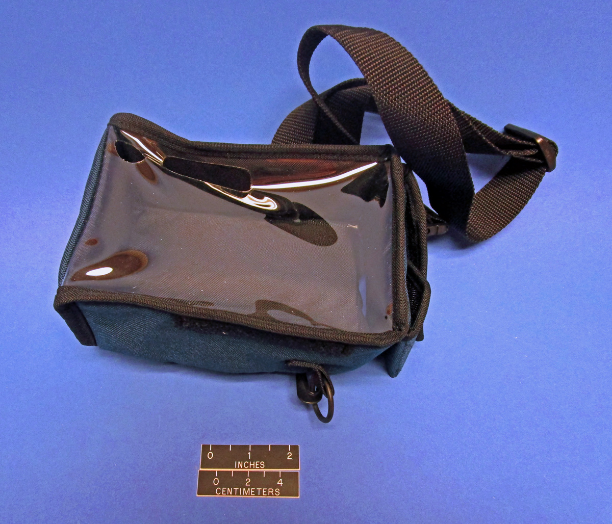
Nylon Ballistic Cloth Carrying Case with strap |
| PS-009736-001 110-240 VAC Power Cord |
Provides direct power to the TR-4 or TR-5 Receivers from a 110-240 VAC 50/60 Hz source |
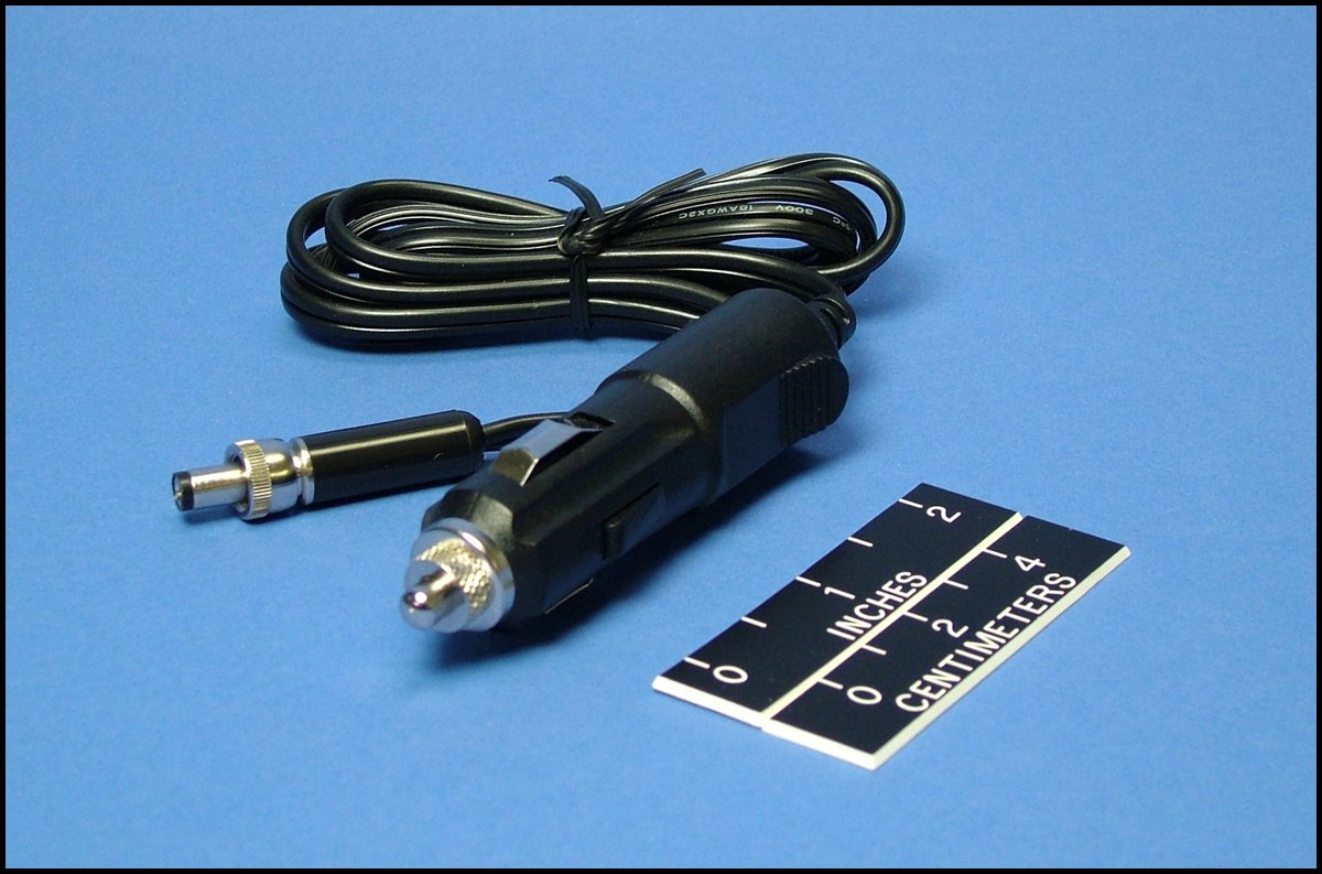
| PS 007248-001 12 VDC Power Cord |
12 VDC Power Cord with "cigarette lighter" plug for powering the TR-5 from a 12VDC battery |
| TSC-1 |
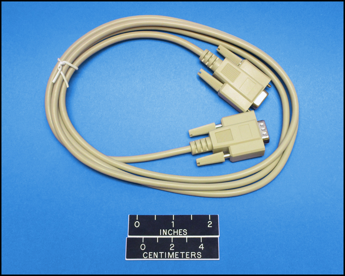
Programming Cable. A DB9 male to DB9 female cable used to transfer parameters and data file between the TR-5 and user PC |
TR-5 Data Acquisition System
The TR-5 can be configured into a complete data acquisition system. The entire system can be deployed in the field to receive and data log telemetry data on a continuous or scheduled basis. The transmitter frequencies, date, time, pulse period, signal strength are logged into memory for later downloading by the researcher. The system operates in a fully unattended mode for the collection of any pulse coded data such as temperature, heart rate, activity level, mortality or simply presence or absence information. The system collects any data encoded into the pulse period of the transmitter but does not collect bearings or positional data. To function as a data acquisition system the following components are recommended and must be procured separately:
TR-5 Kit
Option 320 Data Acquisition Option
RC-9 Instrument Case
RP-7 Field Power Pack
RP-14-110 110-120 VAC Wall Charger for the RP-7
AND
An appropriate antenna and coax cabling must be procured separately. Most system users select an omni-directional antenna such as the RA-6B, RA-10, or RA-5A (see section on receiving antennas for fixed stations. The appropriate coax cable length and connectors must be selected.
Note: The researcher may substitute power supply options or provide alternative antennas or waterproof enclosures for the equipment listed above. The researcher using this approach must integrate the components. The information provided describes a complete system ready to go to the field without the requirement for the researcher to provide any additional components or complete any integration.
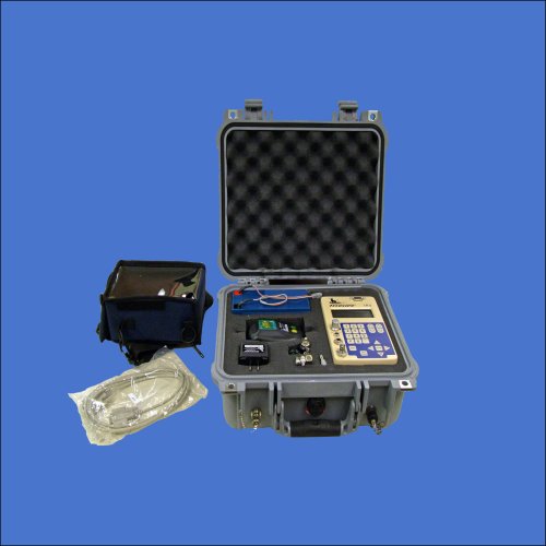
TR-5 shown as part of a Data Acquisition System
Specifications
All specifications are subject to change without notice.
Receiver
| Input Impedance: | 50Ω nominal |
|---|
| Frequency Range: | Any 4 or 6 MHz band between 140 - 225 MHz |
|---|
| Channel Selection: | Keypad entry in 1kHz steps over entire range. Fine tune adjustment in 100Hz steps |
|---|
| Frequency Tolerance: | Standard Temperature Specification (Option 200): ± 500 Hz @ room temperature over 4 MHz band; ± 7ppm deviation from room temperature value over temp range -20° to +60°C.
Extended Temperature Specification (Option 210): ± 500 Hz @ room temperature over 4 MHz band; ± 3ppm deviation from room temperature value over the temp range -30° to +70°C. |
|---|
| Sensitivity: | Manual Mode: -131.5 dBm typical {for 10 dB (S+N)/N}; Data Acquisition Mode: -128 dBm typical {for 10 dB (S+N)/N} |
|---|
| Minimum Discernible Input Level: | -150 dBm (0.007µV) typical. |
|---|
| Pulse Detection Level: | Manual Mode: better than -130 dBm; Data Acquisition Mode: better than -127 dBm |
|---|
| Image Rejection: | 25 dB typical. |
|---|
| Adjacent Channel Rejection: | >40 dB (10 kHz channel spacing). |
|---|
| Dynamic Range: | 40 dB typical (no gain adjustment); >100 dB (gain control range). |
|---|
| RF Overload Protection: | Protection to 250 mW input signal provided internally. |
|---|
General
| Data Acquisition Memory: | Approximately 1 Megabyte non-volatile RAM |
|---|
| Audio Output: | Internal Dynamic Speaker; Panel mounted 1/4" Stereo Phone Jack. Internal speaker
disabled when phone plug inserted. Lightweight headphones supplied standard |
|---|
| Audio Output Impedance: | 8Ω nominal (capable of operation with headsets and speakers with impedances
between 4 and 600Ω |
|---|
| Case Construction: | Housing, Weather Resistant Aluminum with removable battery pack. Ballistic
cloth Carrying Case (Navy blue) |
|---|
| Dimensions: | Receiver Only: 7.0 L x 4.35 W x 2.45 H inches (17.8 L x 11.1 W x 6.2 H cm);
Receiver with battery pack: 7.0 L x 4.35 W x 3.57 H in (17.8 L x 11.1 W x 9.1H cm.) |
|---|
| Weight: | Receiver Only: 1.2 kg; receiver w/ battery pack: 1.65 kg. |
|---|
| Gain Control: | Separate RF and AF gain controls |
|---|
| Front Panel Features: | Weather Resistant Housing (splash proof); Serial Communications Port (DB-9 connector for RS-232); External Power Jack; 1/4" Audio Jack (will drive 8Ω headphones); on/off audio gain control; BNC antenna connector; 21 key custom membrane keypad; 4 line x 20 character LCD display - Operating Temp: -20° to +70°C. |
|---|
Power Supply
| External Power: | 10.5 - 18 VDC |
|---|
| Standard Battery Pack: | 8 AA size cells (12 V w/alkaline cells; 9.6 V w/NiCad cells). |
|---|
| Current Requirement: | Power Switch 'off' (memory backup 20 µA typical from standard battery pack. Note: Memory maintained by internal battery when no other power source is available. Power Switch 'on' Standby: 35 mA maximum; Receive Mode 80-125 mA (depending on RF/AF gain selected); Backlight adds up to 40 mA to current requirement |
|---|
TR-5 Accessories
Programming Accessories
| (no image available) |
Windows based software used to program frequencies and associated transmitter parameters into the TR-5 receiver and recover stored data from a TR-5 with Option 320 (Data Acquisition).
|
 |
TPC-1 Programming Cable
A Data transfer Cable (DB9 pin male to DB9 pin female) is used in conjunction with the TR-5PI Parameter Interface to transfer parameters and data files between the TR-5 and the user's PC.
|
Cases
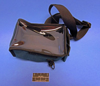 |
RC-7 Carrying Case
Navy Blue, Ballistic Cloth, with Strap.
|
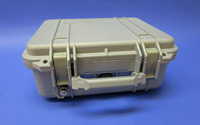 |
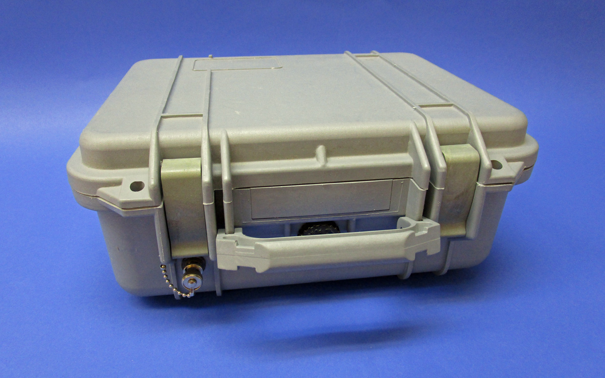
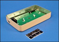
RC-9 Instrument Case
Water-tight, dust proof, lockable case with o-ring seal. Supplied with custom foam interior for placement of a TR-5 receiver and one or optionally two RP-7 12 VDC Power Packs sold separately. Provides a portable weather resistant housing for a TR-5 Data Acquisition System and power packs. Includes internal cabling, adapters, bulkhead BNC connector (with exterior female connection) for attachment of the coax cable or antenna, and an external power input jack. Dimensions: Outside 13 X 12 X 6 inches, Inside 12.25 X 9.25 X 5.25 inches. Weight: 6.0 lbs.
|
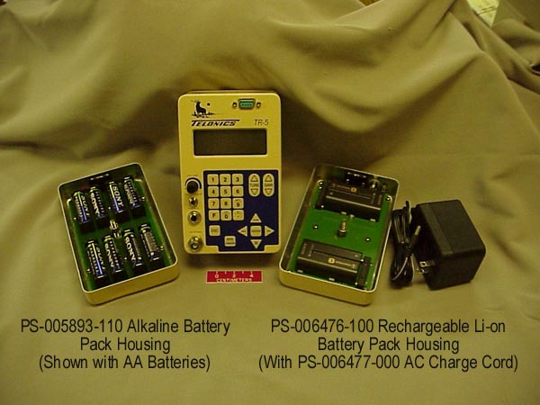
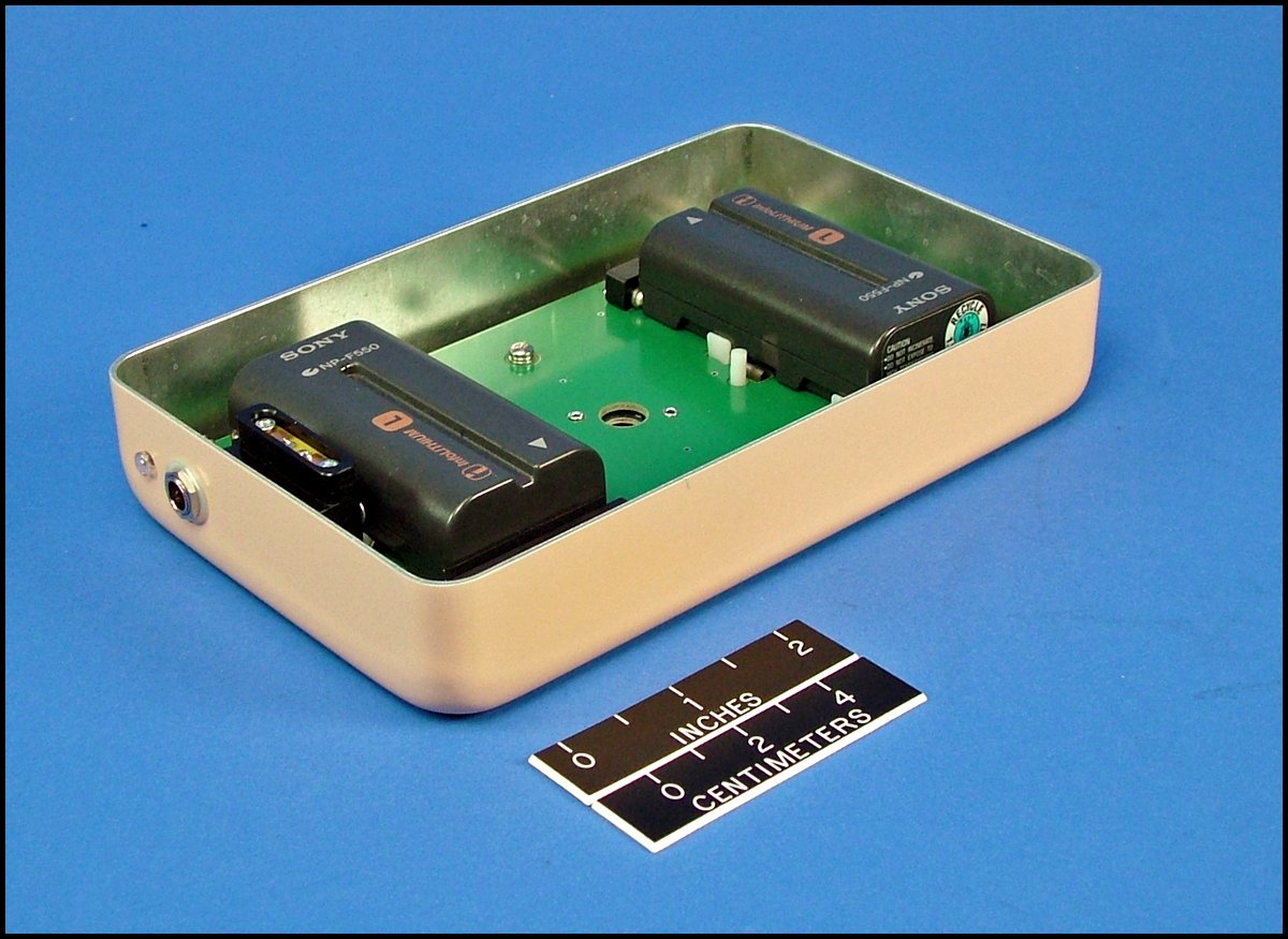
TR-5 Receiver shown with a standard alkaline battery pack (comes with all TR-5 Receivers) and an additional optimal rechargeable battery pack and its charge cord.
Power Supply Options
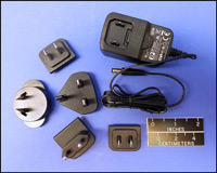 |
PS-009736-001 110-240 VAC Power Cord
Provides direct power to the TR-4 or TR-5 Receivers from a 110-240 VAC 50/60 Hz source. |
 |
PS-007248-001 12VDC Power Cord.
Used to power TR-5 Receiver from a 12 volt DC, negative ground electrical system (automobile battery). The plug on this cord requires a cigarette lighter on the power source.
|
 |
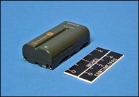
PS-006476-100 Rechargeable Li-Ion Battery Pack
A direct replacement for the Alkaline Primary Battery Pack which comes with all TR-5 Receivers. This option provides the user with the most advanced and energy dense rechargeable power system available today. Note that Li-Ion systems do not have the "memory" problems associated with the Nickel-xxx electrochemical systems of the past. This battery pack contains two independent batteries for redundancy and is capable of running the TR-5 unit for 24 hours without the display backlight and 18 hours with the backlight turned on. The recharge time for the system is just 4 hours. This option comes with its own charger, the PS006477-001 AC charge cord and includes two of the PS006478-001 rechargeable Sony Li-Ion batteries. No special tools are required for installation.
|
 |
PS-006476-110 Rechargeable Li-Ion Battery Pack Housing
As above, but supplied without the PS006478-001 Li-Ion Batteries
|
 |
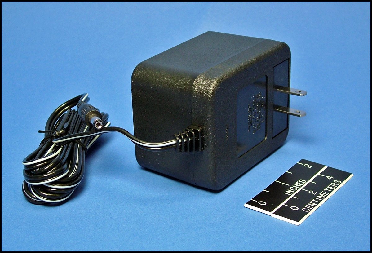
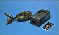
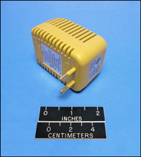
PS-006477-001 AC Charge Cord
This special replacement charge cord is used for charging the PS-006476-100 Battery Pack Rechargeable Li-Ion Battery Pack from any 110-120 VAC 50/60 Hz. outlet power source. This heavy-duty cord is designed specifically to charge both Li-Ion batteries while installed in the PS-006476 battery Pack. Please note this is not the same as the PS-009736-001 AC Power Cord used to operate the TR-5 from a 110-240 VAC 50/60 Hertz wall current.
|
 |
PS-006478-001 Li-Ion Battery
This is a replacement battery (one battery) for the PS-006476 Li-Ion Battery Pack. Two of
these batteries are contained in the PS-006476-100.
|
 |
PS-006479-001 Li-Ion Battery Charger
This charger can be used to charge a single PS-006478-001 battery directly when not installed in the PS-006476-100 or PS006476-110 Rechargeable Battery Packs.
|
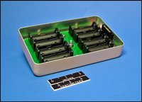 |
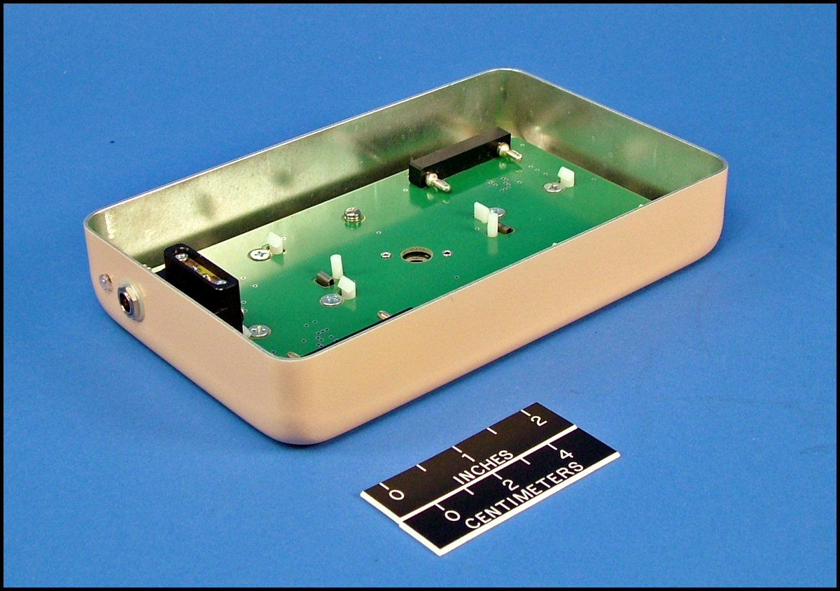
PS-005893-110 Alkaline Battery Pack Housing
This is a replacement housing for the 8AA Alkaline battery pack housing which comes with the TR-5 Receiver. This is the housing only and does not include the 8 Alkaline batteries.
|
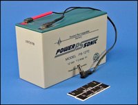 |
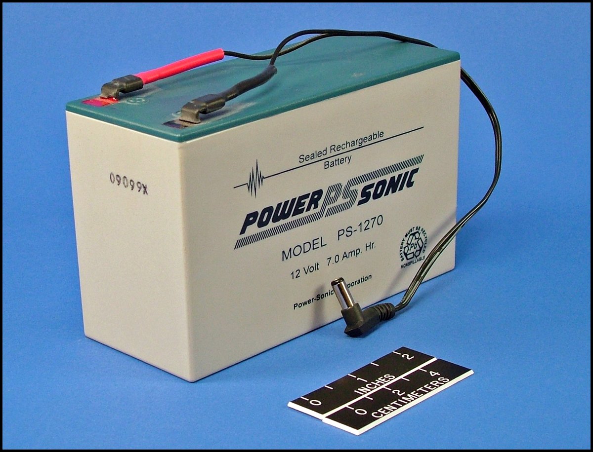
RP-7 Field Power Pack
12 VDC. 7 Ampere-hour field power source. Sealed lead-acid, high impact case. 90 day warranty. Dimensions: 6.0 X 2.6 X 4.0 inches. Weight: 5.5 lbs. Designed for use in the TR-5 Data Acquisition System (see RC-9 Instrument Case). One RP-7 Power Pack will power the TR-5 for approximately 77 hours with TR-5 current requirement at 90 mA. Current requirement depends on RF/AF gain selected and backlight on versus off. Two RP-7 Power Packs will fit within the RC-9 Instrument Case along with the TR-5. Requires PS-008861-001 charger (purchased separately). International customers may also require additional power outlet adapters and AC Step down Transformer (RP-5).
|
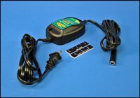 |
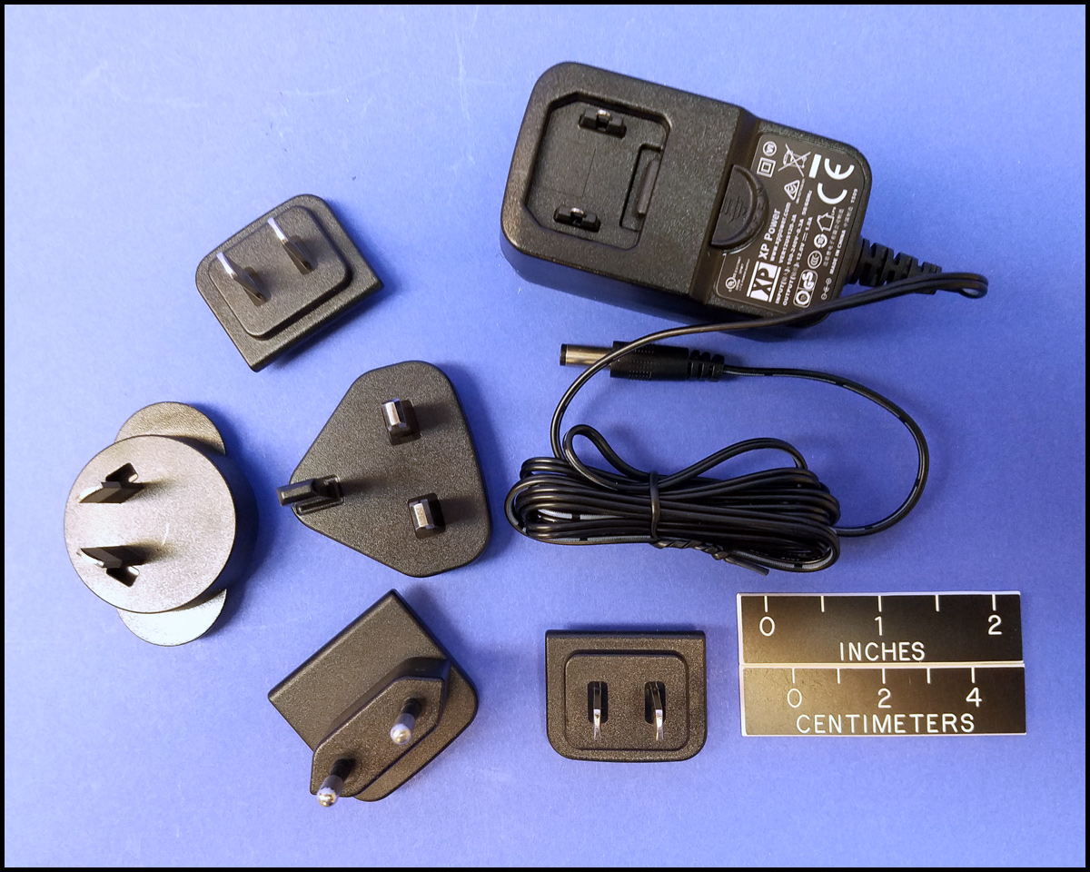
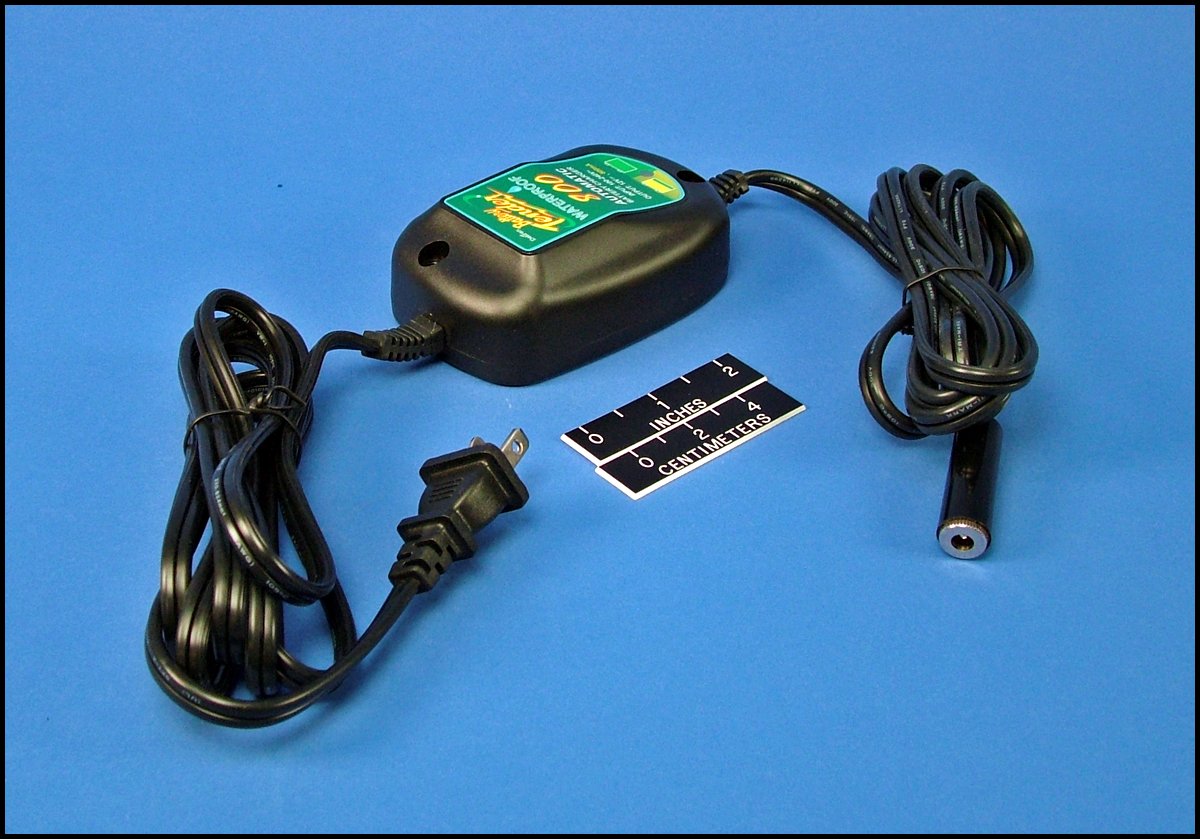
PS-008861-001 Charger
110-120 VAC, 12 VDC, 800 mA for charging RP-7 Field Power Pack. Note: For international customers (excluding Canada), adapters are required.
|
 |
PS-000527-001 (RP-5)
220/240 VAC to 110/120 VAC voltage converter, 50W maximum.
|
 |
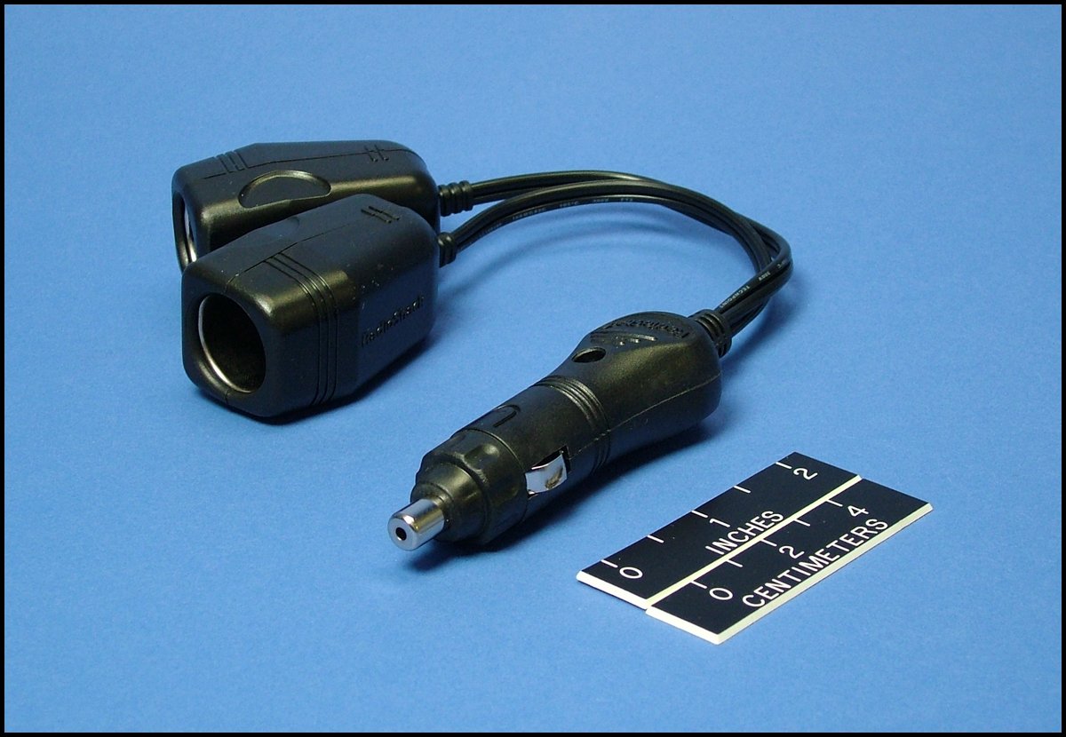
ADP-2 12 VDC Outlet Adapter.
One cigarette-lighter plug on one end, two cigarette-lighter jacks on other.
|
Audio Accessories
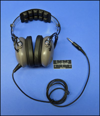 |
RH-2 Headphones
High quality, noise canceling, low impedance headphones designed for heavy use. Supplied with a straight cord, 0.25" plug, and foam filled ear seals.
These headphones replace the RH-1 headphones.
|
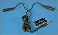 |
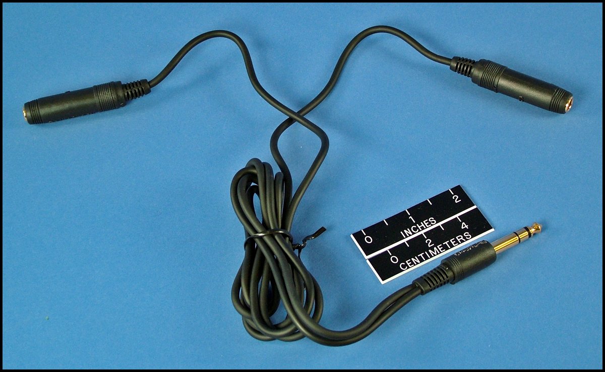
RW-4A "Y" Adapter
Allows the use of two low-impedance headsets with a single receiver.
|
Audio Enhancement Accessories
 |
Telonics TNR-3000 Noise Reduction Unit is small, rugged, and lightweight; and is suitable for operation in vehicles or at fixed sites.
Users can power the TNR-3000 with either an internal 9 volt battery, a car power jack, or an AC power source, depending on application requirements. Telonics supplies the appropriate cables and transformers separately.
|
Manual
Service Commitment
Since 1970, Telonics has built a reputation based on product quality, product support, service, and customer satisfaction. Telonics strives to produce the highest quality products, and to support those products accordingly.
Because of extreme conditions and the unpredictable nature associated with most telemetry applications, problems occasionally arise. Most problems can be resolved quickly. In all cases, we hope to be able to work in partnership with users to resolve problems to the user's satisfaction and to uphold our demonstrated commitment to excellence. If problems should arise, all products must be returned to our factory for failure analysis.
Warranty - Show
Telonics warrants its products to be free from defects in material and workmanship for a period of one year from the date acquired. Telonics does not warrant batteries.
If a defect occurs, return the equipment to us within the proper time frame at the following address: TELONICS, 932 E. IMPALA AVENUE, MESA AZ USA 85204-6699. Damage to any equipment resulting from misuse, accidents, unauthorized service, extreme conditions, or other causes, is excluded from this warranty. Telonics does not assume responsibility for loss or damage to equipment during shipment. Telonics does not assume responsibility for delays resulting from shipment on commercial or private carriers. We insure all equipment shipped from our facility and suggest that shipments to Telonics also be insured.
Upon the timely return to our facility, if defective, the product will be replaced or repaired at our discretion at no cost to the customer. This remedy is the exclusive remedy. This product is supplied without any further warranties or conditions, expressed or implied, including warranties of merchantability, quality or fitness for particular reason or those arising by laws, statutes or trade usage or course of dealing.
The entire risk, as to the results and performance of the product, is assumed by the customer. Neither Telonics, nor its suppliers, shall have any liability to the customer or any other person or entity for any indirect, incidental, special, or consequential damage whatsoever, regardless whether Telonics has been told of the possibility of such damages or that such damages might be foreseeable. Telonics has no responsibility or liability for the claims of any third party. The maximum aggregate to the customer, of Telonics and its suppliers, shall not exceed the amount paid by the customer for the product.