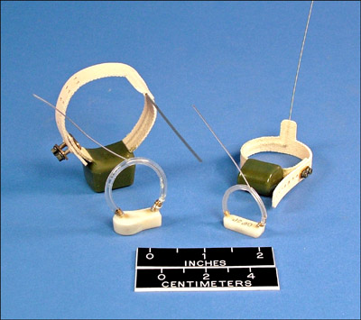
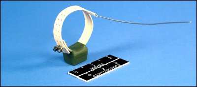
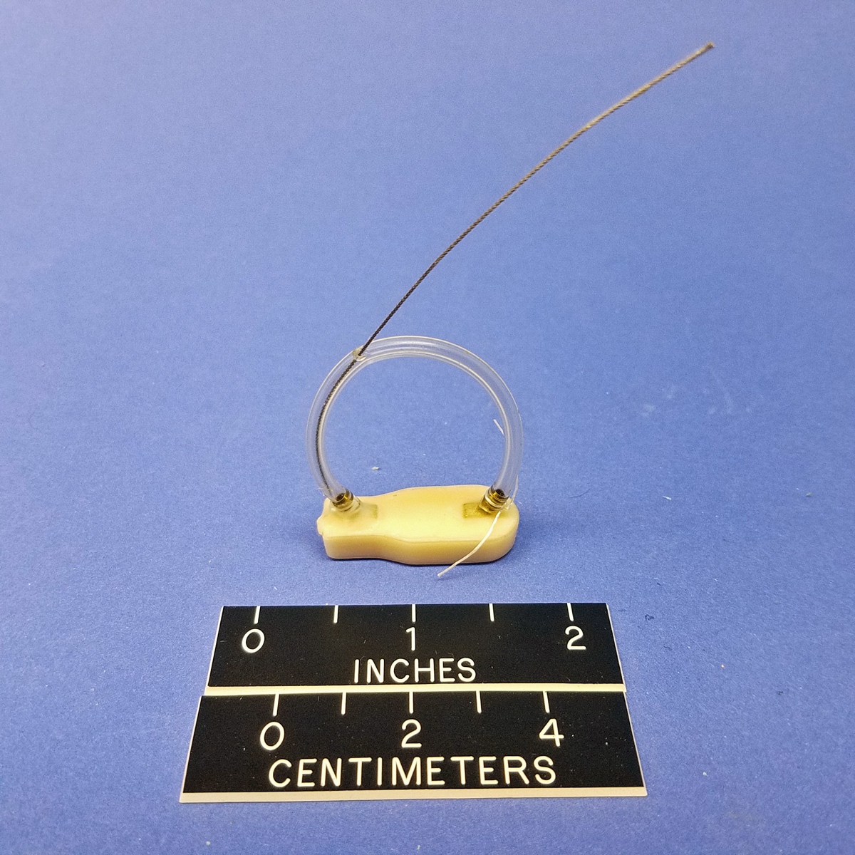
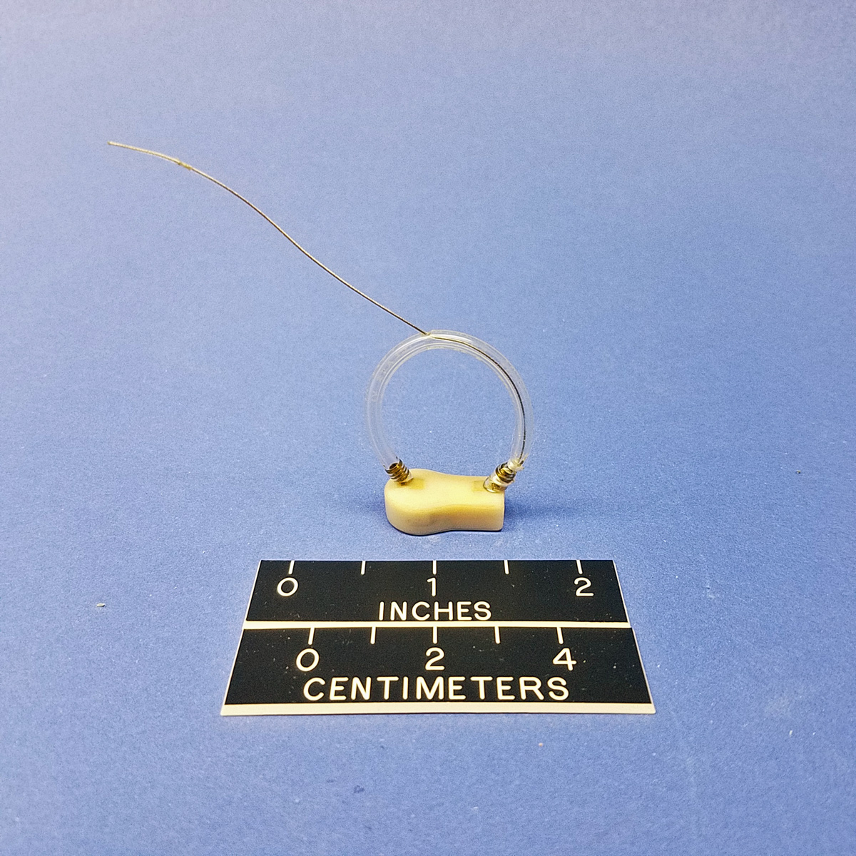
The CHP VHF Transmitting Subsystem includes the following main components: internal digital, radio frequency electronics comprising the transmitter, power supply (battery), exterior packaging, transmitting antenna, and attachment. A refurbished Subsystem is warranted as if the Subsystem was purchased new, unless otherwise stated.
Telonics warranties only the following with respect to the Subsystem:
1.1 The exterior packaging integrity of CHP subsystems with external antennas are warranted for the operational life of the Subsystem, up to a maximum of three (3) months from the date of initial shipment of the Subsystem by Telonics.
Limitations:
Although each Subsystem is supplied with a power supply in the form of a battery, Telonics does not manufacture batteries (electrochemical cells), and therefore cannot warranty the battery lifespan, mechanical integrity or other battery performance issues. However, Telonics conducts extensive testing of all types of electro-chemical subsystems to determine suitability to the application. Once an electrochemical system is chosen for a configuration, testing procedures are employed at Telonics to evaluate every individual battery that is installed in each transmitting subsystem. Even using these advanced testing procedures it is not possible to determine a specific battery's lifespan ormechanical integrity.
Telonics conducts tests to assure that each unit is transmitting at the power level selected by the user. Actual range performance is a system characteristic dependent upon numerous conditions including receiver sensitivity and noise figure, receiving antenna tuning and pattern, transmitter antenna integrity, line of sight conditions in the field, and vegetation and habitat conditions and other factors specific to individual study sites. Therefore it is not possible to warranty a minimum range that will be achieved for units deployed in the field.
"Packaging integrity" as applicable to 1.1 above, is limited to normal wear as encountered when attached to the animal.
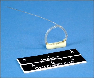
Antenna breakage statement
It is the purchaser's obligation to make certain that it orders the correct size and type of Subsystem for the particular type and size of animal that the Subsystem will be applied to, and no warranty is expressed or implied for any failure to meet operational specifications due in whole or in part to use of an incorrect size or type of Subsystem.
No warranty is expressed or implied with regard to abnormal events or damage due to human actions such as gunshot damage, vehicle encounters, etc. Further, no warranty is expressed or implied with regard to damage resulting from misuse, accidents, unauthorized service, extreme conditions, or other causes not specifically enumerated herein.
The entire risk, as to the results and performance of the Subsystem, is assumed by the customer. Neither Telonics, nor its suppliers, shall have any liability to the customer or any other person or entity for any indirect, incidental, special, or consequential damage whatsoever, regardless whether Telonics has been told of the possibility of such damages or that such damages might be foreseeable. Telonics has no responsibility or liability for the claims of any third party. Telonics' and its suppliers' maximum aggregate liability shall not exceed the amount paid by the customer for the Subsystem.
Exercising the Warranty
If a defect occurs, return the Subsystem to Telonics within the applicable time frame noted above at the following address: TELONICS, 932 E. IMPALA AVENUE, MESA AZ USA 85204-6699. Telonics does not assume responsibility for loss or damage to equipment during shipment. Telonics does not assume responsibility for delays resulting from shipment on commercial or private carriers. We insure all equipment shipped from our facility and suggest that shipments to Telonics also be insured. Customer shall arrange for and pay all shipping, insurance and related charges incurred in the shipment of Subsystems to and from Telonics under this warranty.
Upon the timely return to our facility within the applicable time frame noted above, if the exterior packaging integrity and/or internal electronics (excluding batteries) are defective, the Subsystem will be replaced or repaired, at Telonics' sole discretion, at no cost to the customer, other than shipping charges. This remedy is the exclusive remedy. This product is supplied without any further warranties or conditions, expressed or implied, including warranties of merchantability, quality or fitness for particular reason or those arising by laws, statutes or trade usage or course of dealing.
The above warranty extends only to the original purchaser and does not cover any Subsystem which is resold or otherwise transferred from the original purchaser to another party. The warranty will be extended to customers who purchase the Subsystem directly from a Telonics-authorized distributor.