Telonics ST-16 Argos Certified Module
The information below on discontinued products is provided for individuals who are still using these older systems. Product descriptions may be time sensitive or even outdated. Please contact Telonics if you have questions.
Introduction
The ST-16 RF Module is a small and versatile radio frequency (RF) assembly which has been certified with Argos for use with the Argos System. The unit has been designed to provide a one half watt (0.5 W) output power (see Specifications section for details). The ST-16 is available as a separate component for those researchers who wish to interface an RF Module with their own digital control circuitry. It is important to understand that when the RF Module is sold for use with an uncertified controller, it is necessary for the user to certify their complete digital assembly with ARGOS prior to any deployment. This is the user's responsibility even though the ST-16 RF Module has previously been certified in conjunction with Telonics digital control circuitry.
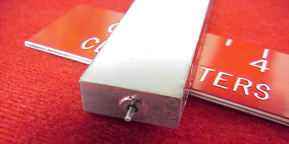
ST-16 Feedthru End |
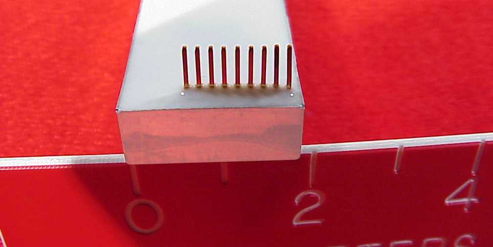
ST-16 Header End |
For a detailed Autocad® outline drawing of the ST-16 in PDF format, click here.
Input/Output Pins
The ST-16 RF Module is supplied with a single hermetic feed-through positioned on one end of the unit which provides the RF output to the user supplied antenna. All other I/O signals are accessed through a 9 pin header protruding from the unit on the opposite end of the RF Module.
Pin 1 is closest to the rail corner with the remaining pins numbered sequentially toward the center of the rail. Individual pin functions are as follows:
| PIN # |
TYPE |
FUNCTION |
| Pin 1 |
Input |
Power and signal ground, common to the rail. |
| Pin 2 |
Input |
Phase 1 modulation (0 vdc to 3.3 vdc). |
| Pin 3 |
Input |
Phase 2 modulation (0 vdc to 3.3 vdc).Pins 2 and 3 are the bi-phase modulation inputs. There
are pull-downs (~2 meg) in the module on these two lines. The modulation inputs will drive 3.3 vdc HCMOS devices,
therefore, the modulating signals must comply with standard family specifications for these devices in order to
guarantee operation over temperature. |
| Pin 4 |
Input |
Loop Enable (0 vdc = off; 3.3 vdc = on). This pin is normally held low until time to begin the
transmit sequence. There is a 2 meg pull-down in the transmitter on this line. To begin the transmit sequence,
this line must be taken high 100 msec before the TX enable line. To guarantee operation over temperature, this high
must be 2.5 vdc minimum. Maximum input cannot exceed +Vbatt. |
| Pin 5 |
Output |
TX Sense (0 vdc = off; 3 vdc = TX on). This output line is low when the transmitter is off and high
when the transmitter is on with the low being 0 vdc and a high being 2.5 vdc minimum, 3.0 vdc nominal. This line is
a signal line only, to be used for the required ARGOS shutdown circuitry and cannot source current. |
| Pin 6 |
Input |
TX Enable (0 vdc = off; 3.3 vdc = on). This pin is normally held low and has a 2 meg pull-down on
the line. Drive the line high when it is time to transmit (same operating specifications as the Loop Enable). When
the transmission is complete, drive both the Loop Enable and TX Enable low simultaneously. |
| Pin 7 |
Input |
TX Shutdown (H1Z = normal; GND = shutdown). Under
normal operating circumstances, this line must not be loaded in any way (high Z). If the transmitter exceeds the
ARGOS maximum for a single transmission (1 second as detected from the TX sense line), then the TX Shutdown line
must be driven low to turn off the transmitter and suppress any further transmissions for the minimum ARGOS shutdown
period. |
| Pin 8 |
Input |
+Vbatt (+battery input, 4 vdc to 7.5 vdc). This is the battery input for the transmitter. The ST-16
is specified for operation from 4 vdc to 7.5 vdc. |
| Pin 9 |
Input |
Power and signal ground common to the rail. |
Notes on Usage
- Battery input can also be wired to the front of the unit.
- Loop enable = High must precede TX enable = High by 100 msec.
- TX sense cannot source current and must have A H1 Z load. Do not bypass with any capacitors larger than .01µf.
ST-16 Specifications
Mechanical
| Dimensions | 3.020 L x .720 W x .300 T inches |
|---|
| Weight | Approximately 7 grams, full cast unit approximately 13 grams |
|---|
| Frequency | 401.650 MHz ( In accordance with ARGOS specifications) |
|---|
| Operating Temperature Range | Option 004 (-40 to +70° C) or Option 005 (-40 to +60° C) |
|---|
| Storage Temperature Range | -60 to +80° C |
|---|
| Humidity | 90% Non-condensing |
|---|
Power Output/Peak Current
(50Ω impedance) | 525 mw/385 ma at 7.3 vdc, 400 mw/355 ma at 6.0 vdc, 200 mw/315 ma at 4.0 vdc |
|---|
| Voltage | +4.0 vdc to 7.2 vdc |
|---|
| Quiescent Current | <45 Ωa (operating) <5 Ωa (shutdown) |
|---|
| Case Polarity | Negative (-) Ground |
|---|
| RF Output Impedance | 50Ω |
|---|
Service Commitment
Since 1970, Telonics has built a reputation based on product quality, product support, service, and customer satisfaction. Telonics strives to produce the highest quality products, and to support those products accordingly.
Because of extreme conditions and the unpredictable nature associated with most telemetry applications, problems occasionally arise. Most problems can be resolved quickly. In all cases, we hope to be able to work in partnership with users to resolve problems to the user's satisfaction and to uphold our demonstrated commitment to excellence. If problems should arise, all products must be returned to our factory for failure analysis.
Warranty - Show
Telonics warrants its products to be free from defects in material and workmanship for a period of one year from the date acquired. Telonics does not warrant batteries.
If a defect occurs, return the equipment to us within the proper time frame at the following address: TELONICS, 932 E. IMPALA AVENUE, MESA AZ USA 85204-6699. Damage to any equipment resulting from misuse, accidents, unauthorized service, extreme conditions, or other causes, is excluded from this warranty. Telonics does not assume responsibility for loss or damage to equipment during shipment. Telonics does not assume responsibility for delays resulting from shipment on commercial or private carriers. We insure all equipment shipped from our facility and suggest that shipments to Telonics also be insured.
Upon the timely return to our facility, if defective, the product will be replaced or repaired at our discretion at no cost to the customer. This remedy is the exclusive remedy. This product is supplied without any further warranties or conditions, expressed or implied, including warranties of merchantability, quality or fitness for particular reason or those arising by laws, statutes or trade usage or course of dealing.
The entire risk, as to the results and performance of the product, is assumed by the customer. Neither Telonics, nor its suppliers, shall have any liability to the customer or any other person or entity for any indirect, incidental, special, or consequential damage whatsoever, regardless whether Telonics has been told of the possibility of such damages or that such damages might be foreseeable. Telonics has no responsibility or liability for the claims of any third party. The maximum aggregate to the customer, of Telonics and its suppliers, shall not exceed the amount paid by the customer for the product.
